Week 8 - Challenge 4 - Coin Holder Design
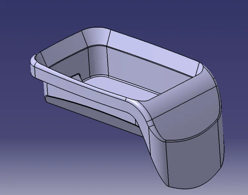
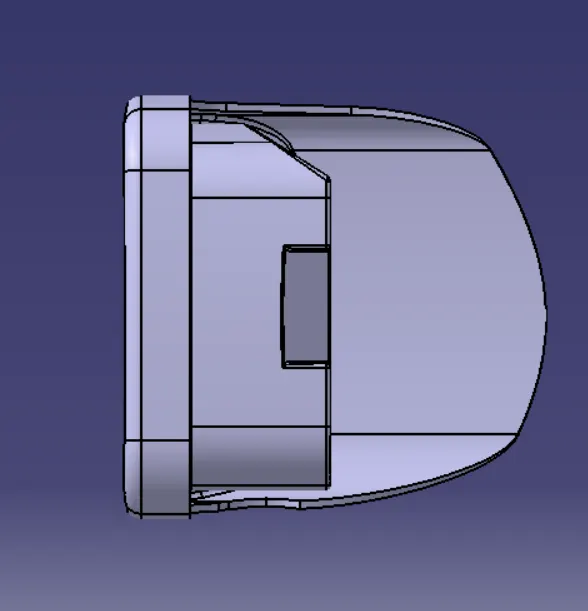
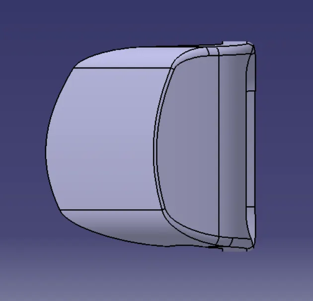
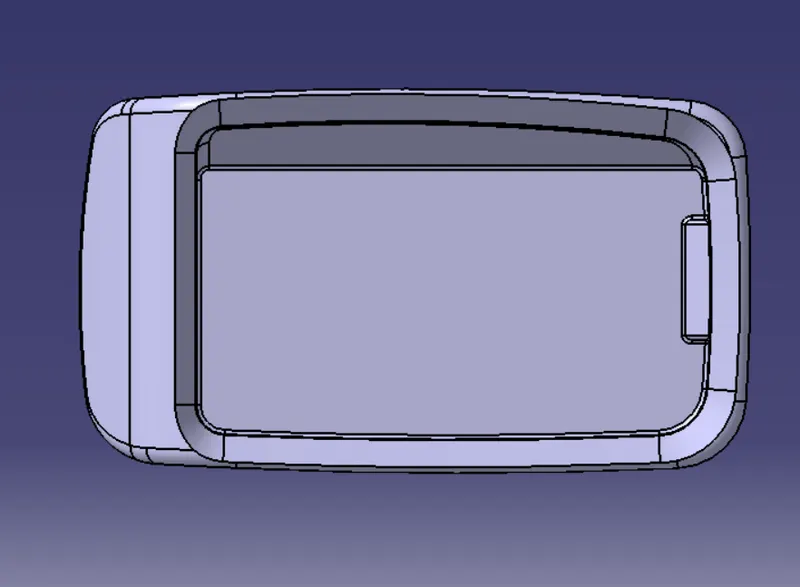
We will see how to create the tooling axis and Draft analysis of a Coin Holder, along with the creation of the Coin holder using surface designing.
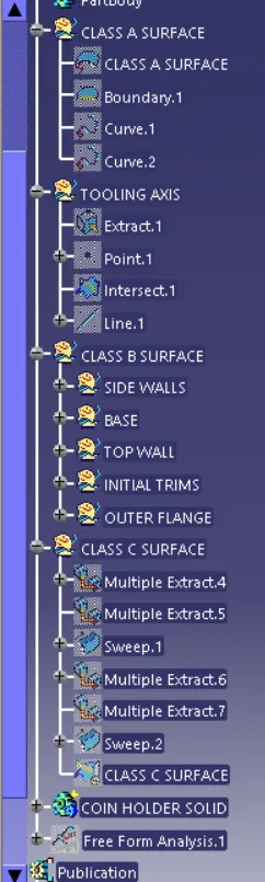
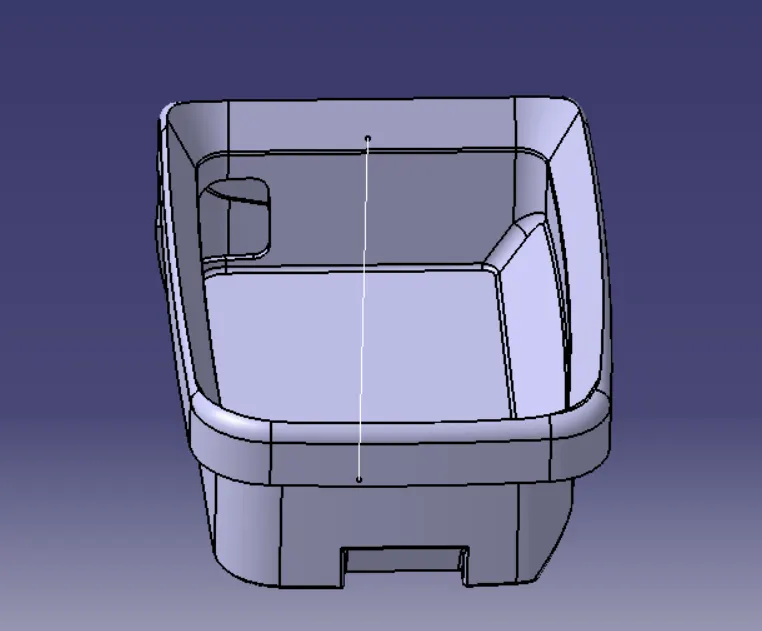
- The first important part to be done is to create the tooling axis, so that it will show us on how to create the drafting analysis as well as give the drafting angle.
- It is done by extracting the base of the Class A Surface, then placing a point in the centre of it.
- Next the intersection of the part is taken which allows us to see the proper tooling axis.
- once the tooling axis is created, we shall move on to the next stage, which is creating the Class B Surface and Class C Surface for the Given Class A Surface.
- This allows us to create the solid of the given Class A Surface.
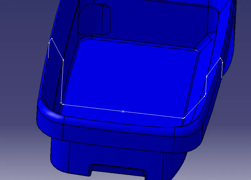
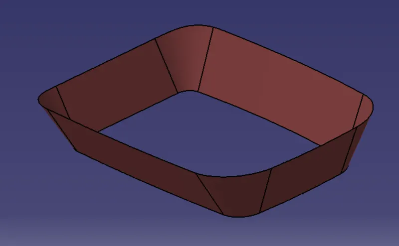
- In this process, we first create the Class B Surafce, whcih includes the base, side walls, outer flange, and the top wall.
- First the side walls are created using commands such as Extract, untrim, extrapolate, trim, and then finally offset.
- extract is used to extract the surface from the Class A Surface, then it is Untrimmed, which gives us the required shape to be cut off, then we trim it to the desired shape, then we extrapolate it which extends the walls of the surface, then finally we offset it to the rewuired thicknesss.
- THis is done for the other parts as shown below.
- Then the required parts are trimmed to give us the final B surface., after whcih we give edge fillets to it.
- Next we move on to creating the C surface of the component.
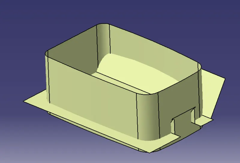
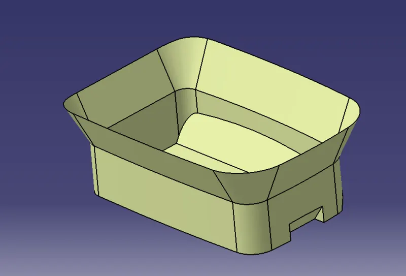
- While creating the C Surafce, we should keep in mind that the connnecting surface for the B and A surface should be pulled perpendicular to the tooling axis, it is done because the shape is uneven and cannot be tooled along the tooling axis.
- Here the C Surface is done using the command called sweep, where the reference boundary is taken and is swept along the surface of the side walls.
- this gives us the required c Surface., it is also done for the hole cutout inside the part.
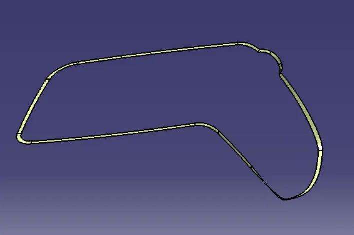
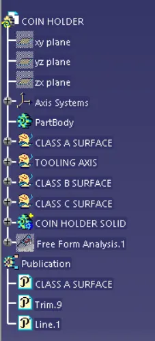
- After this we finally join both the surfaces creating the completed part.
- It is then made into solid by converting into mechanical part design, where solid option is used to create the given figure.
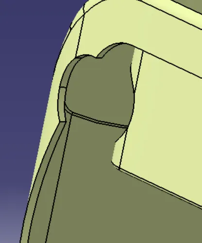
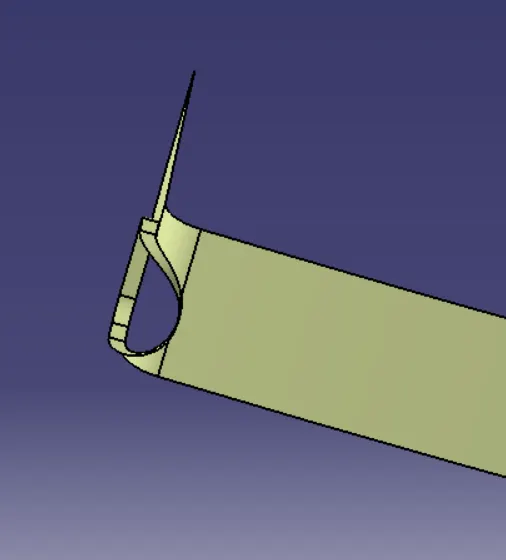
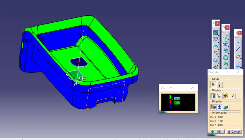
- The next main part that we do is the Draft analysis, where the tooling axis we created will come in handy,.
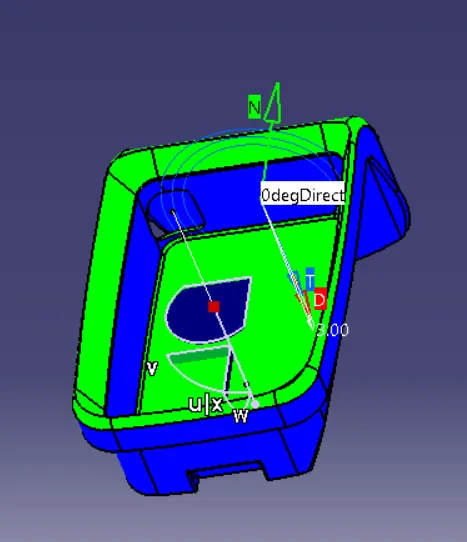
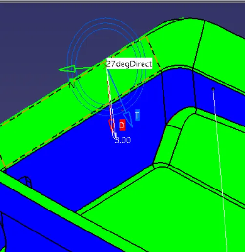
- Draft analysis is done along the tooling axis and the required draft analysis is shown in the figure.
- Green parts show the proepr drafts at 3 degree.
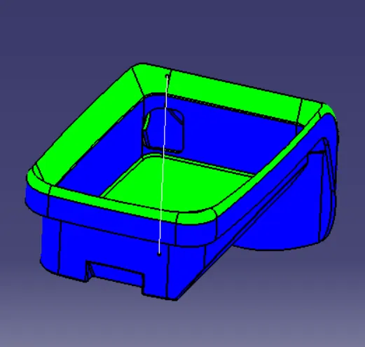
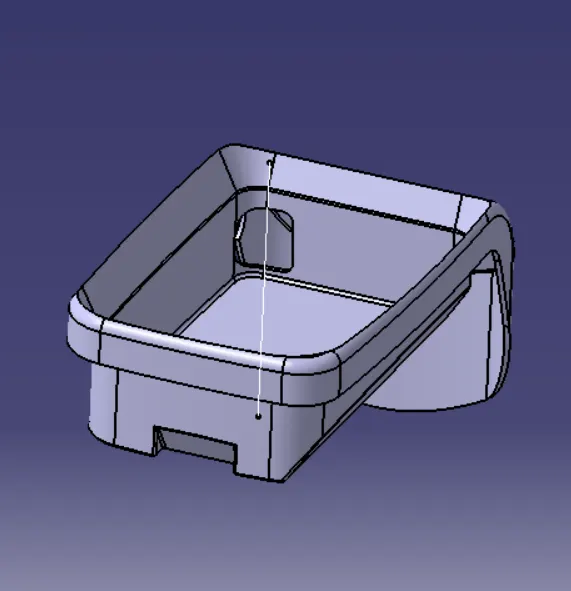
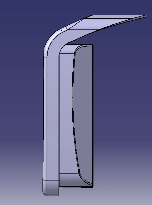
- Final images of the Solid part.