Week 8 - Challenge 4 - Coin Holder Design
AIM: Creating the Center Console Coin Holder design through the given Class-A surface of 2.5 mm thickness with the tooling axis meeting the requirements of the draft angle and at the end performing the Draft analysis on the model.
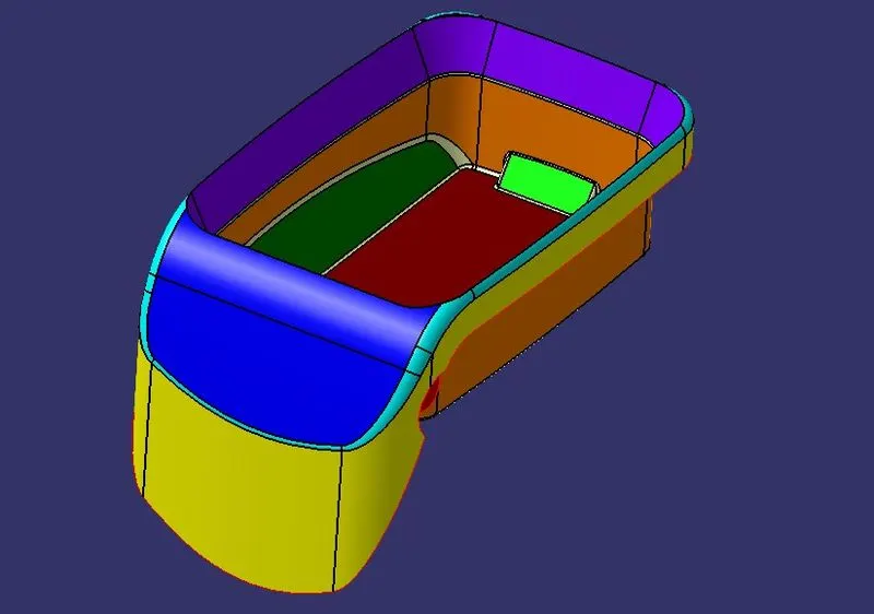
PROCEDURE REQUIRED DRAFT ANALYSIS:
STEP 1: Ensure there is no gap between the two neighboring surfaces.
Operations>Boundary>definition>select component
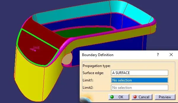
- We can see that there is a gap between the two neighboring surfaces so we have to join the respective surfaces.
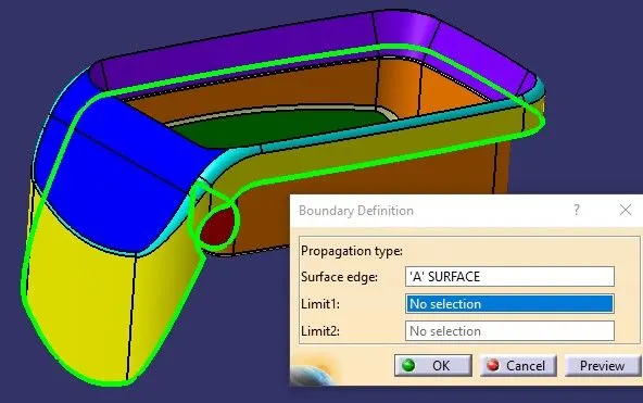
STEP 2: Tooling Axis - The tooling axis is the direction in which the mold or core and cavity are opened.
We have to check all possible tooling directions in all three axes. When we are deciding on the tooling axis we have to make sure that all the faces should be visible to that tooling axis, no face should be hidden.
For this component, the Z-axis will be the best tooling axis as we can see all the faces of the component and can be cleared in the x and y-axis directions.
STEP 3: To make the tooling axis for this model we have to extract the base surface.
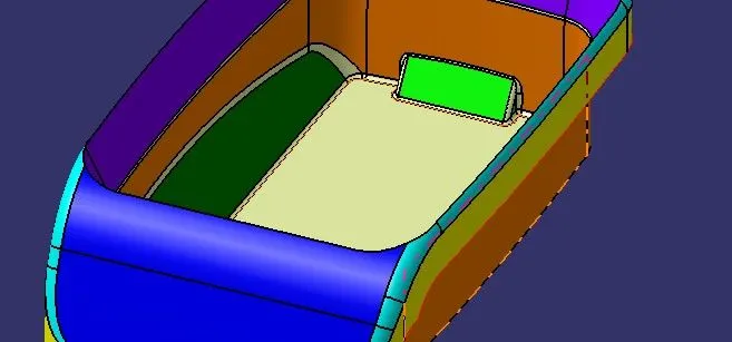
STEP 4: Place a point in the middle of the extracted surface by using on surface point definition at 0mm.
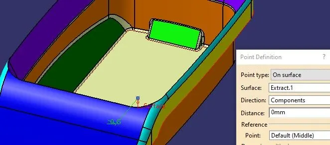
- The point can be viewed below.
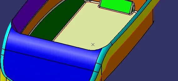
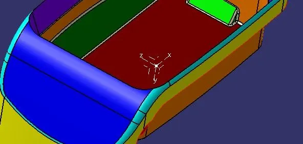
STEP 5: Insert Axis system
STEP 6: Extract an intersecting line with an A-class surface and ZY Plane.
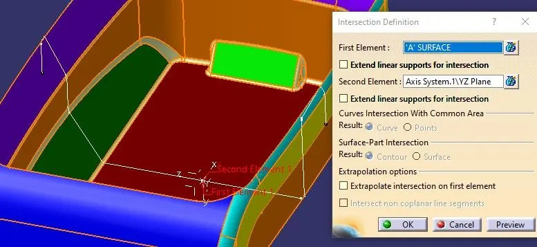
STEP 7:Check the angle between two lines which should not be parallel to each other.
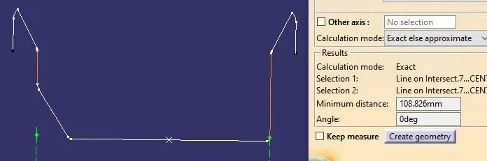
- We can see that the angle between both lines is zero degrees which means that the A-class surface is not drafted.
- There should be a draft of 3 degrees so that when the component is removed from its mold it ejects easily without any friction and scratches.
- For this component where there is zero degrees of difference, it can simply extract a line from a point towards the Z-axis or say parallel to these two lines.
STEP 8: Extracting line from the point towards Z-axis.
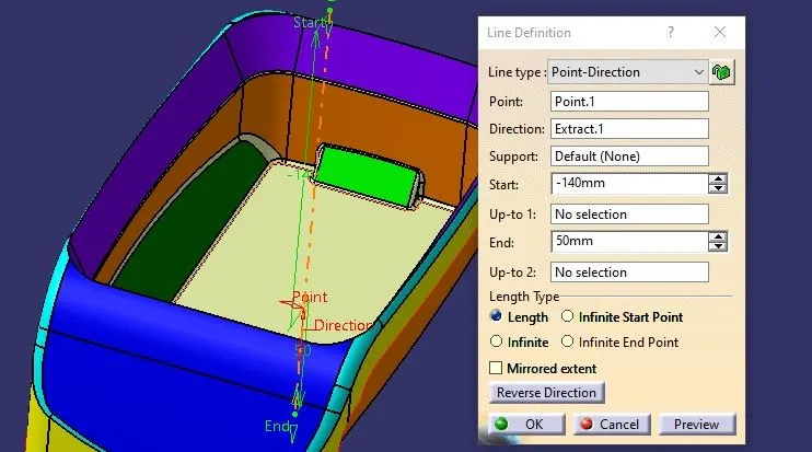
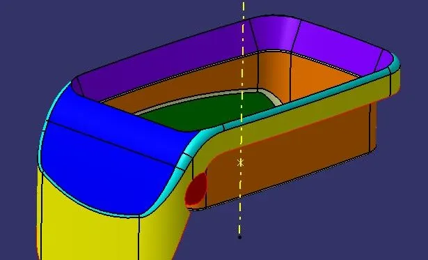
STEP 9: Rename, change color and give thickness to the tooling axis so that it can be easily identified.
PROCEDURE FOR CREATING ‘B’ SURFACE DESIGN:
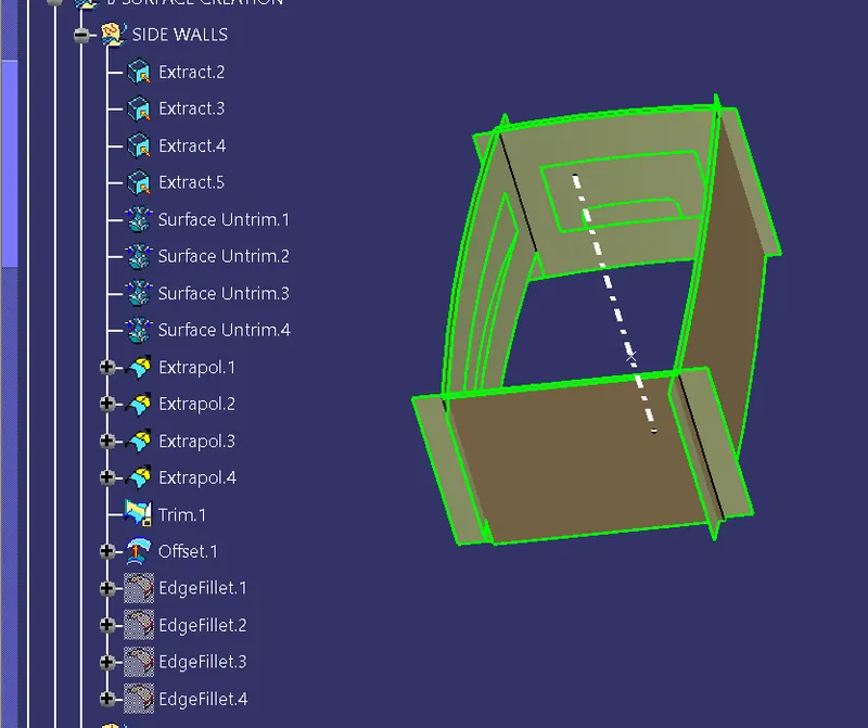
STEP 1: Extracting Surfaces from the Walls of the coin holder.
- Extract the surface
- Untrim that extracted surface
- Extrapolate.
- Offset it inside to 2.5 mm
- Trimming surface.
- Giving fillet
STEP 2: Extracting Surfaces from the base of the coin holder.
- Extract the surface
- Untrim that extracted surface
- Extrapolate.
- Offset it inside to 2.5 mm
- Trimming surface.
- trimming of side walls with the base to get the proper output
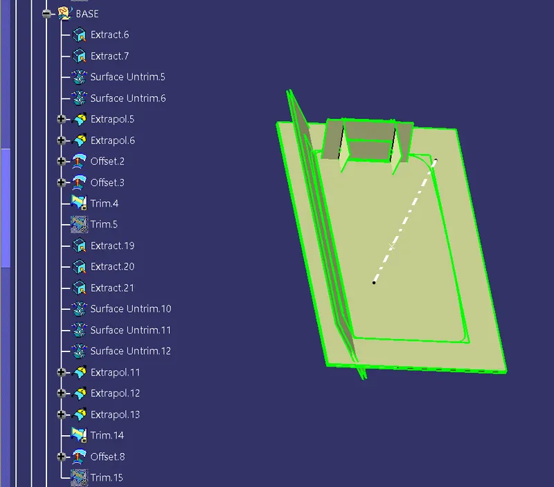
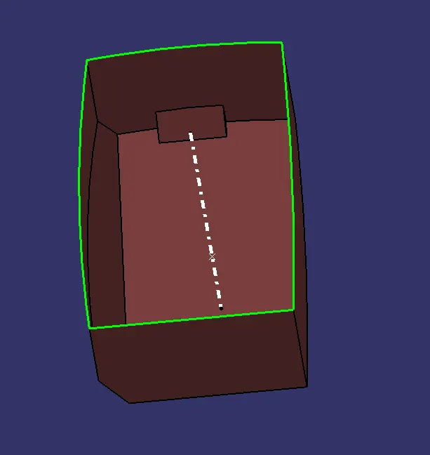
- I got the B surface as an output but I have to make some changes in it to add the fillets features
STEP 3: Extracting Surfaces from the tilted wall of the coin holder.
- Extract the surface
- Untrim that extracted surface
- Extrapolate.
- Offset it inside to 2.5 mm
- Trimming surface.
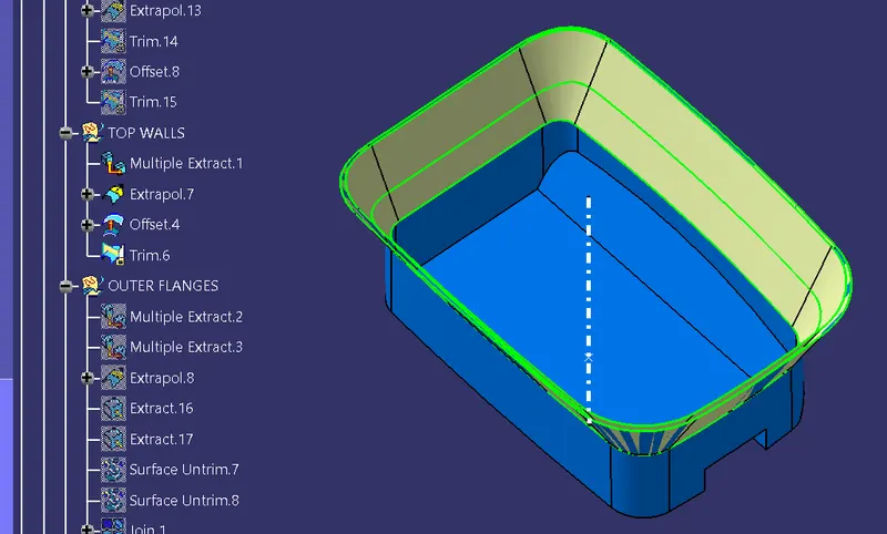
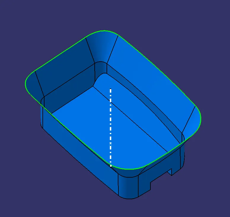
STEP 4: Extracting Surfaces from the outside walls of the coin holder.
- Extract the surface
- Untrim that extracted surface
- Extrapolate.
- Offset it inside to 2.5 mm
- Trimming surface.
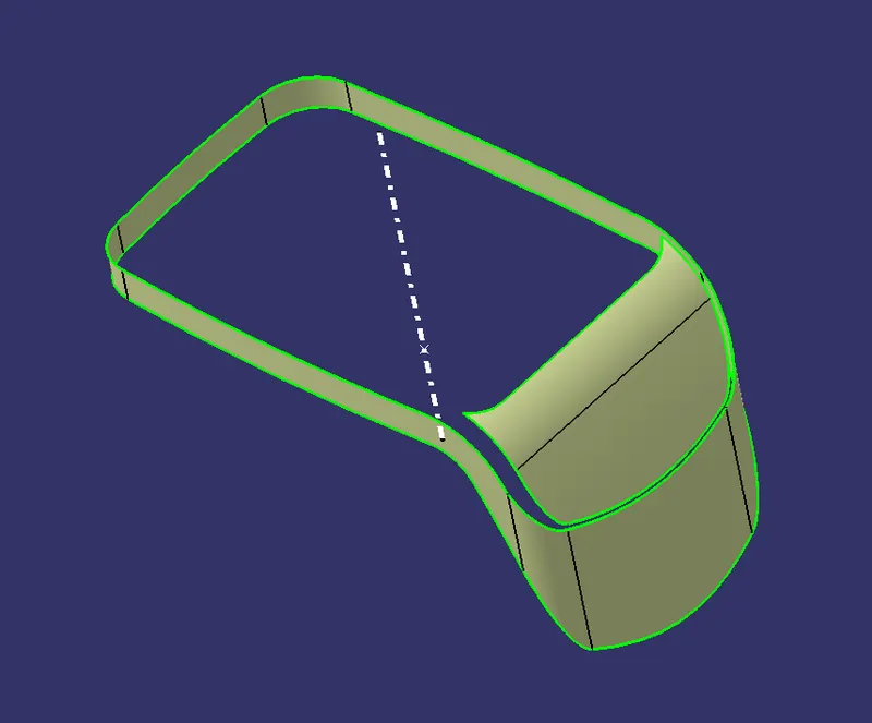
STEP 5: Extracting Surfaces from the slant wall of the coin holder.
- Extract the surface
- Untrim that extracted surface
- Joining two surfaces of the slant wall.
- Extrapolate.
- Offset it inside to 2.5 mm
- Trimming surface.
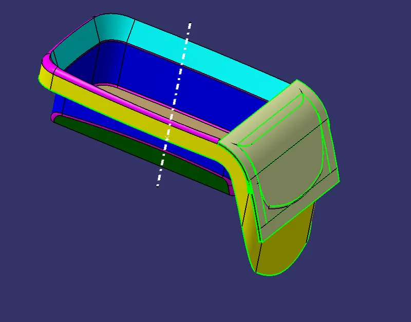
- After trimming outside walls and slank surface together we will get the output as below.
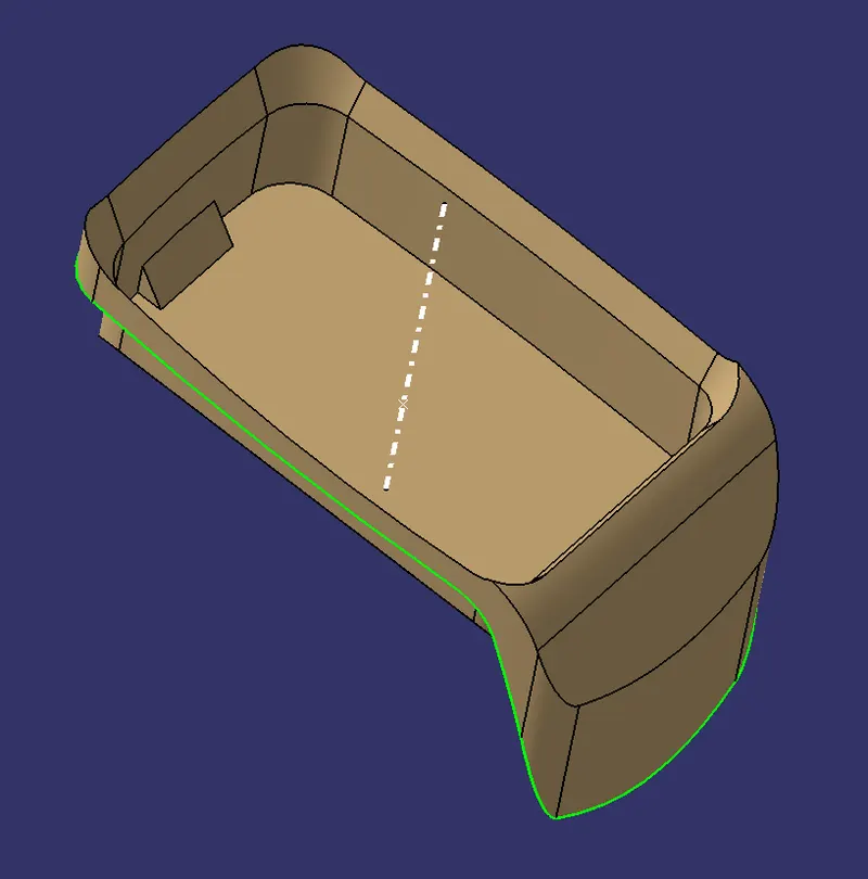
- final timing of horizontal surfacing and timing it with the surface obtained
- I got the complete B surface after adding fillets to it as below
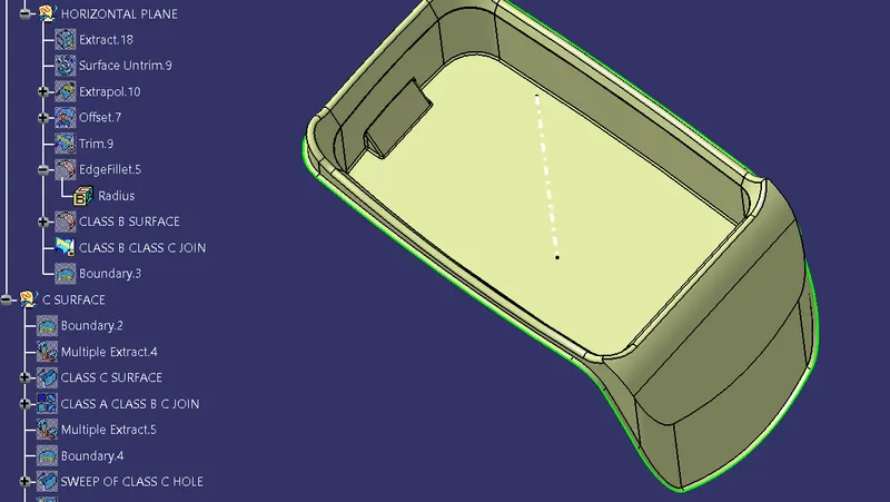
PROCEDURE FOR CREATING ‘C’ SURFACE DESIGN:
STEP 1:
- Extract an intersecting line with A-class surface and ZY Plane.
- Extract an intersecting line with B class surface and ZY Plane.
- Extract a boundary from an A-class surface.
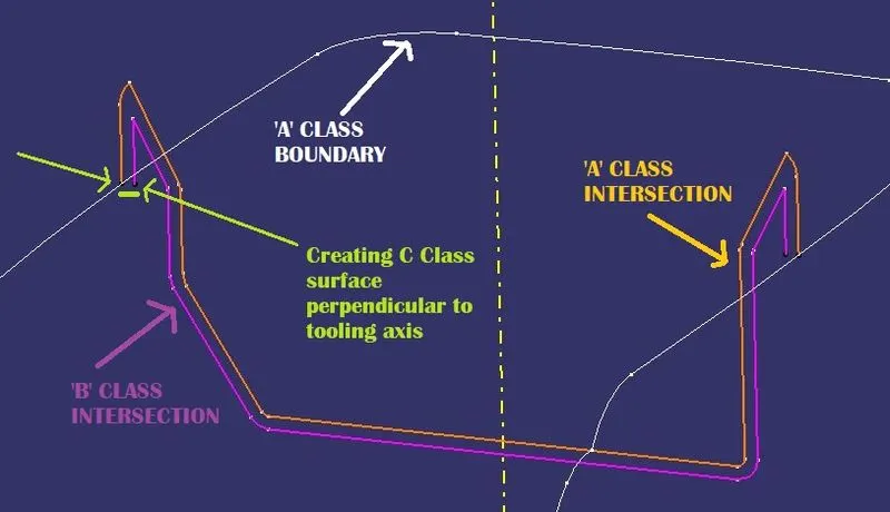
STEP 2: Extracting Sweep with A-class reference surface pane
- After extracting the top wall I swept it 90 degrees
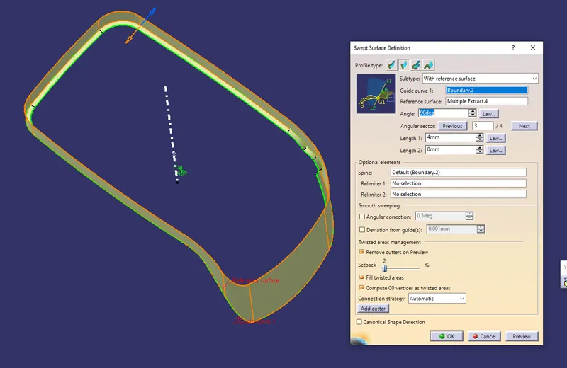
- final output after sweeping as below
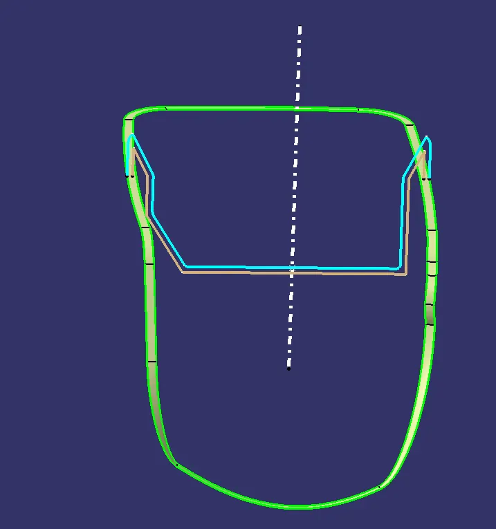
STEP 3: Repeat the Step 1 and Step 2 for Hole in the Coin Holder Component.
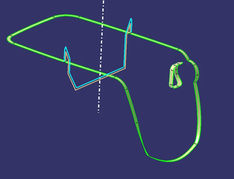
STEP 4: Join the A surface and C (two sweeps) surface.
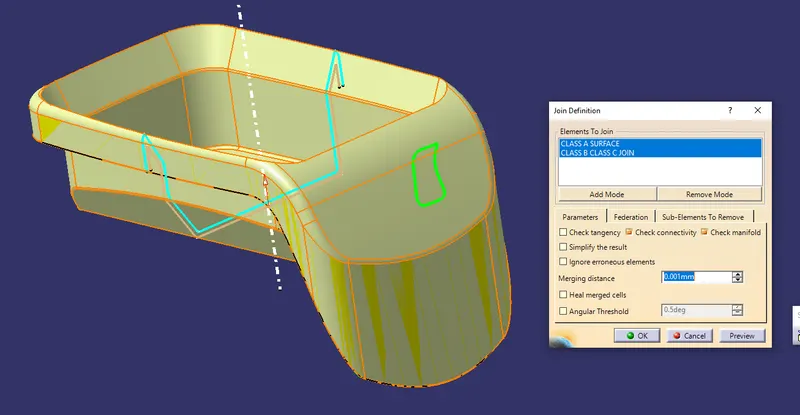
- Extract the side walls which are joining the hole then after sweeping it join them together
STEP 5: Trim these joined surfaces and B surface to get a thickened part.
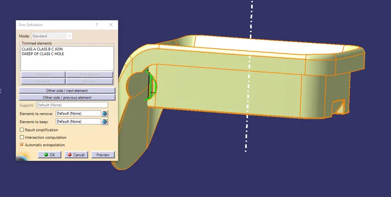
- We can see the thickening C surface after trimming as below -
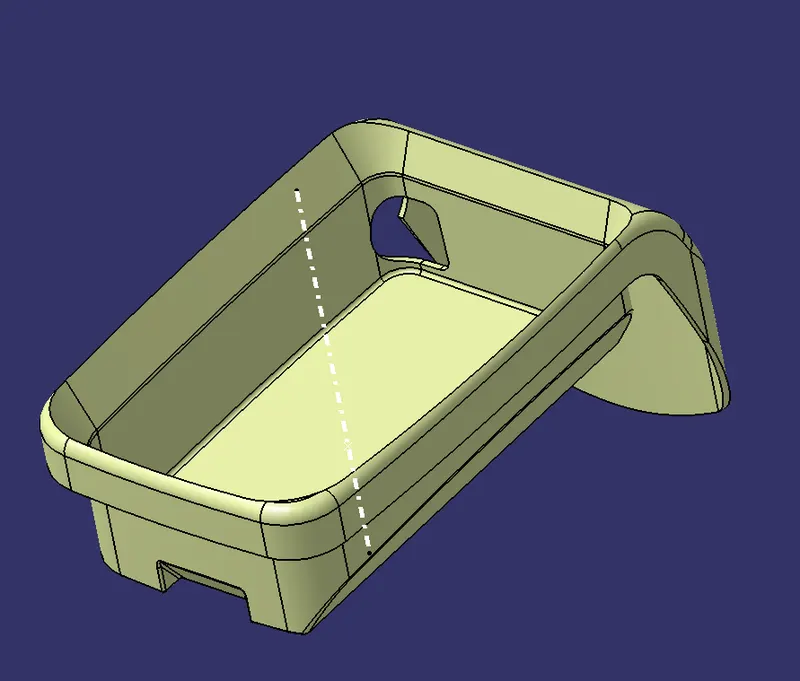
STEP 6: Switch to Part Design Workbench, Define the Part body to make Coin Holder C Surface into a solid component by the surface panel.
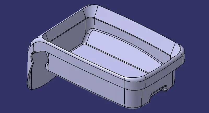
PROCEDURE TO CHECK DRAT ANALYSIS: Check draft analysis on the final part body.
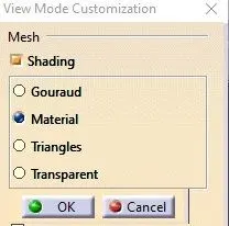
STEP 1: Changing view mode to the material.
View mode>view mode customisation>tick material>ok
STEP 2: Calling Draft Analysis.
Toolbar>Insert>Analysis>Feature Draft Analysis
STEP 3:
- Drag the compass from the draft analysis box on the tooling axis and place it properly.
- Click on locks so the compass will get locked to the tooling axis.
- Click anywhere on the component.
- Click OK.
- Analysis of the color of the failing and passing surfaces.
If a component is showing in a Green color that means our component is ready for manufacture.
NOTE: If we find zero degree or negative degree filing color, we can fix it by changing the draft angle, sweep direction, modifying properly tooling axis, etc.
- Feature Draft Analysis on ‘A-Class Surface.
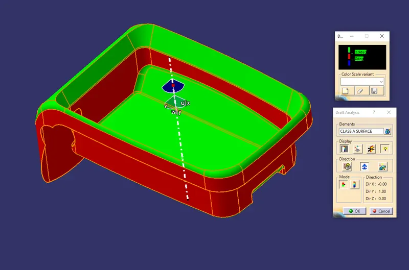
This is the Feature draft analysis on the Class-A surface as some parts are already at 0 degrees so I cannot modify the class-A surface. to modify I need the permission of the class A maker.
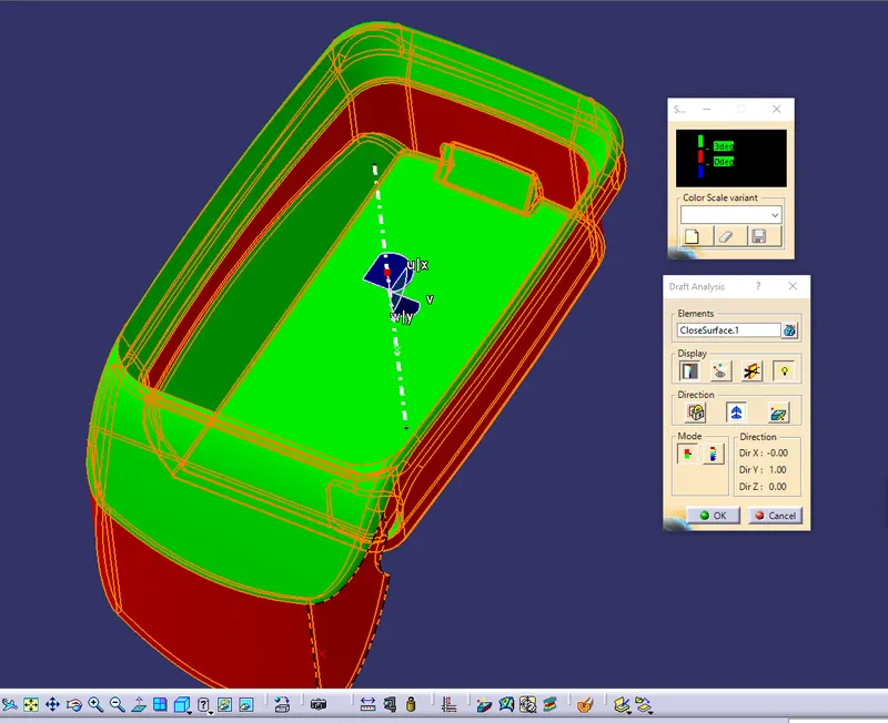
- Feature Draft Analysis Part Body.
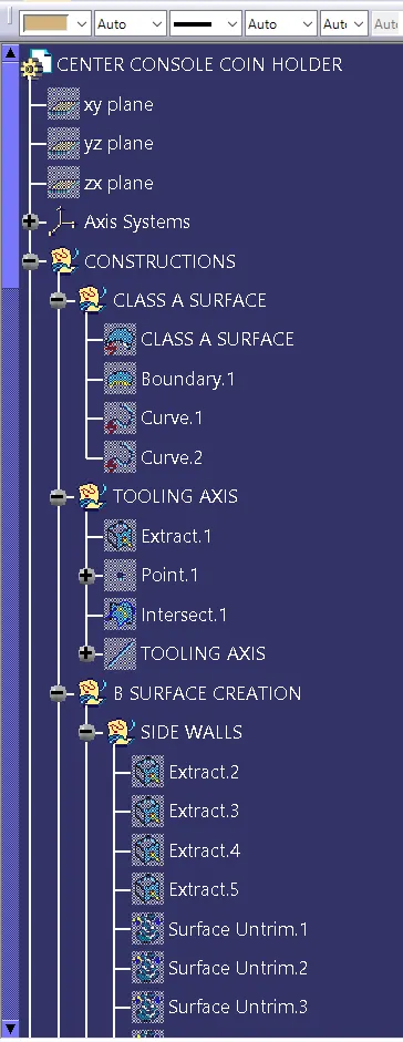
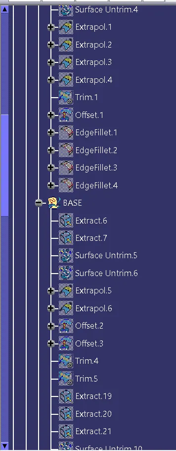
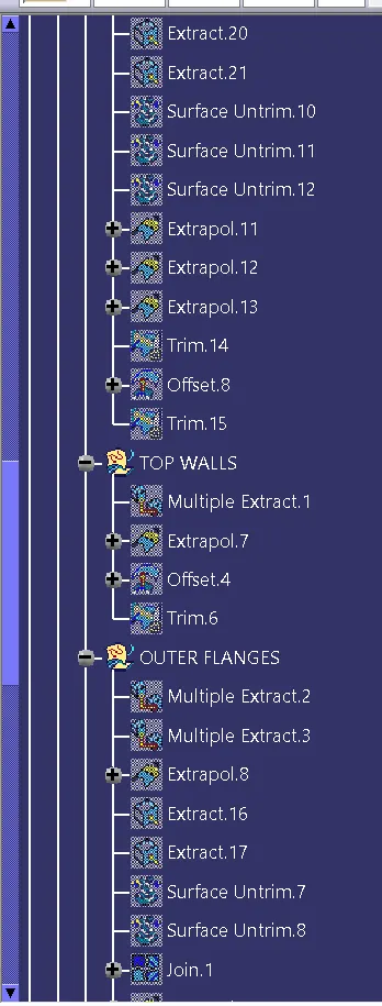
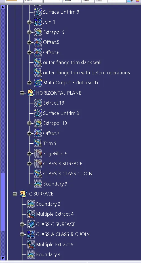
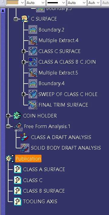
TREE STRUCTURE:-
LEARNINGS :
- Extracting tooling axis.
- Inserting Axis system and Publication
- Extract, Multiple Extract, Untrim, Extrapolate, Offset, Trim, Joining the surfaces.
- Giving Fillet radius to inside and outside Offset surfaces.
- Extracting Boundaries.
- Extracting surface perpendicular to tooling axis.
- Sweep with reference surface panel.
- Joining A and C surface and trimming it from B surface to get the required thicken body.
- Draft Analysis and fixing errors.
CONCLUSION:
We can see that the inside walls of the coin holder component are red after applying feature draft analysis as it is not clearing the draft analysis because the given class-A surface was not drafted by a class-A design engineer.