Week 8 - Challenge 4 - Coin Holder Design
WEEK-8 CHALLENGE-4
COIN HOLDER DESIGN
AIM
This challenge aims to create a tooling direction of the given class-A surface and then to create the solid model and perform draft analysis.
PROCEDURE
Evaluating the given class-A surface
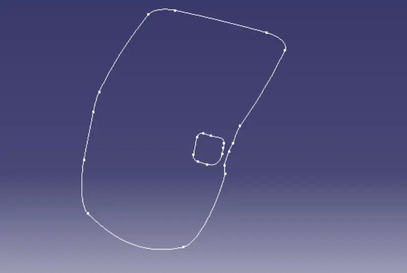
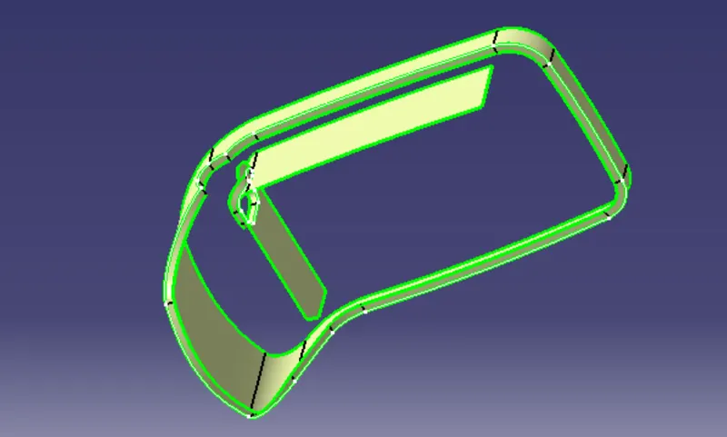
The class-A surface must be evaluated before starting the design and any irregularities/ discontinuities must be reported and rectified. This can be done by using the JOIN/ BOUNDARY command.
Defining the tooling direction
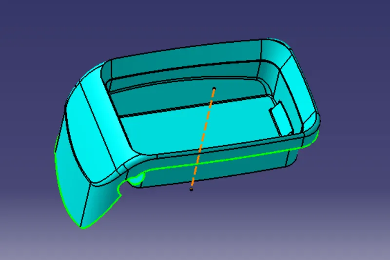
The ideal tooling direction has to be the direction in which most of the features can be easily cleared. In this case, the initial tooling direction can be assumed in the direction perpendicular to the flat surfaces and the surfaces which might be difficult to clear in this direction are identified and the initial tooling direction has to be modified accordingly. But in this case, the flat surfaces and the critical surfaces are perpendicular to each other. So, the initial tooling direction can be taken as the final tooling direction.
Creation of class-B surfaces
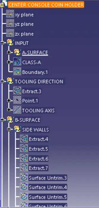
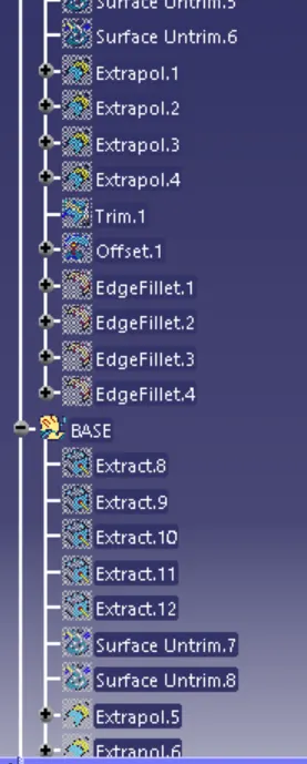
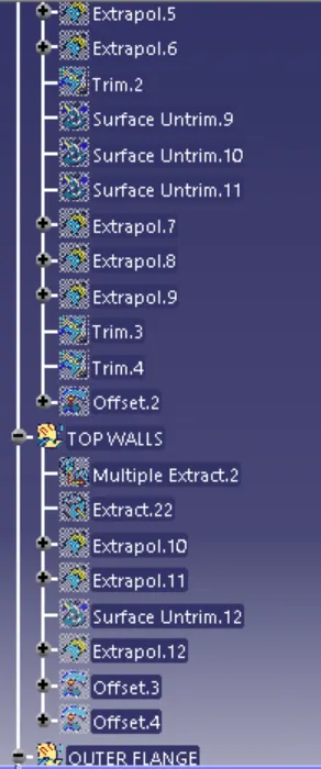
For the class-b surfaces, we extract the class-A surfaces excluding the fillets, and then untrim these surfaces to get the original surfaces. These surfaces are now extrapolated by appropriate distances so that all the surfaces touch each other. Now, the unnecessary faces are trimmed off and the output is offset by thickness value (here it is 2.5mm) in the appropriate direction. This process is repeated for all the features in the coin holder to get the class-B surface.
Creation of class-C surface
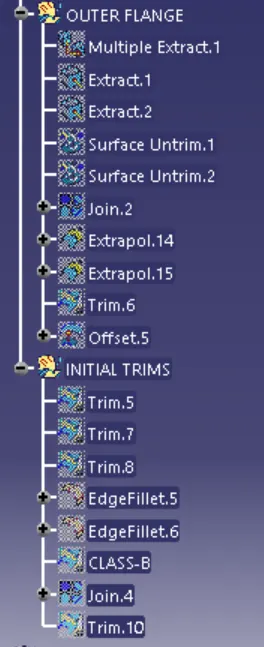
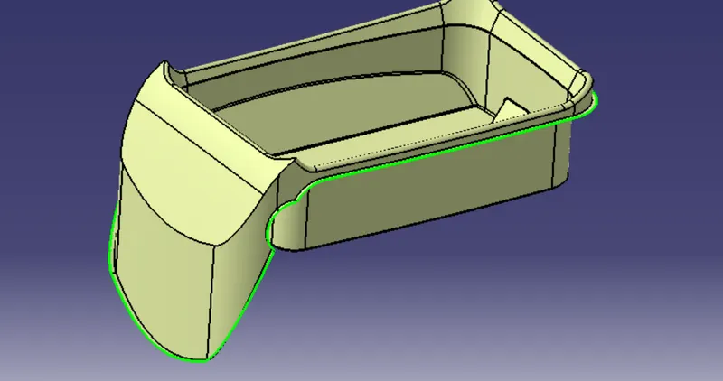
Class-C surface joins the A and B surfaces together. C-surface can be created by using the sweep command where the input is the boundary extracted from the A-surface. The c-surface is now joined to the existing A-surface and the output is trimmed using the B-surface which gives a closed surface (This can be verified using boundary command).
Converting into a solid model
The obtained surface model can be converted into a solid model using the closed surface feature present in the part workbench.
Draft analysis
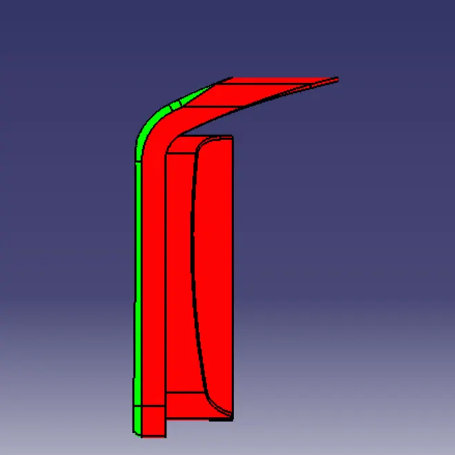
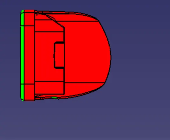
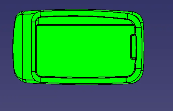
Draft analysis is really important to know the manufacturability of the designed component. Draft analysis of the solid model is performed for the tooling axis obtained earlier.
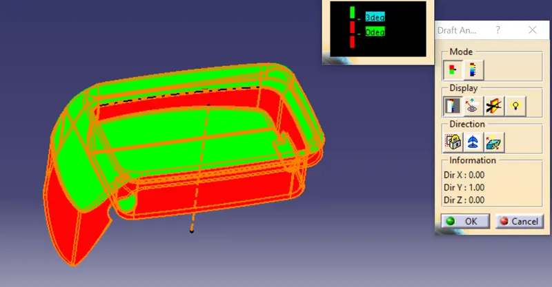
draft analysis of given class-A:
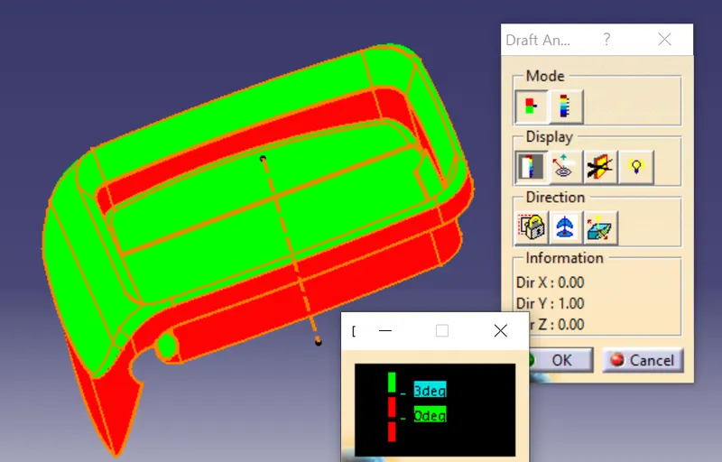
FINAL MODEL
Isometric view Top view
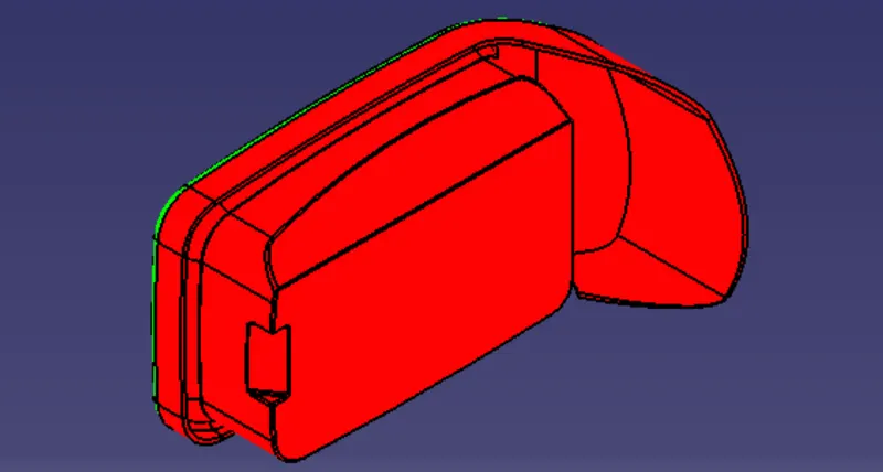
Front view Side view
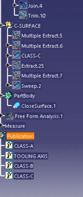
Geometric tree