Week 8 - Challenge 4 - Coin Holder Design
Coin Holder Design
Aim: - The aim of this report is to create the Coin Holder Plastic component through the given Class-A surface in catiaV5 (Computer-aided three-dimensional interactive application).
Objective: -
- To create the coin holder plastic component through the given Class-A surface.
- To create the tooling axis for the coin holder model meeting the requirements of the draft angle.
- To perform a draft analysis on both coin holder Class A and the final model to confirm the appropriate draft angle.
- To publish the Class A, B, and C surfaces and tooling axis using the publication command in the software.
- To explain the bisecting method used in order to create the tooling axis for the coin holder model.
Theory: -
- Tooling axis creation for coin holder model: -
The tooling axis indicates the direction along which the tooling or the manufacturing of the component will be done. In catia, the tooling axis is used to create C surfaces using the sweep option. There are many methods for the creation of the tooling axis and bisecting method is one of them.
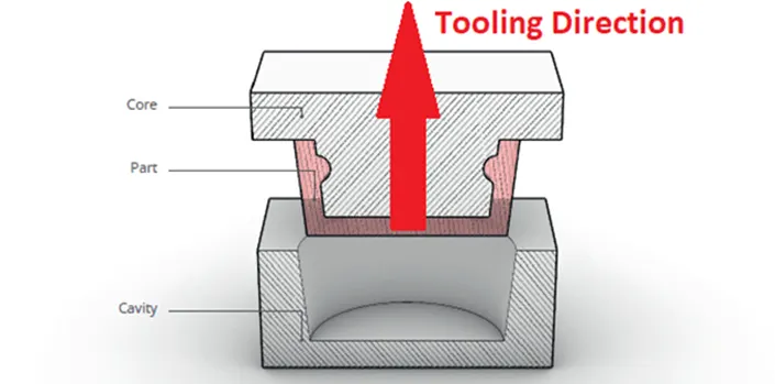
figure 01: - Example of tooling axis direction
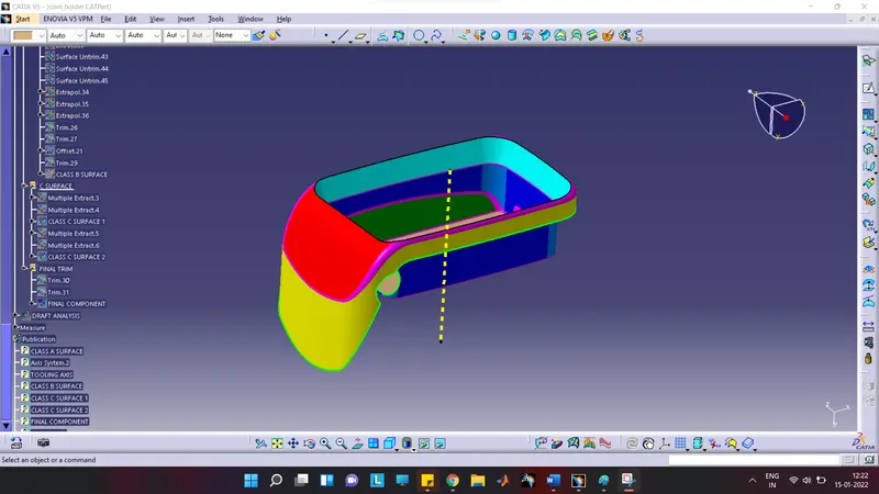

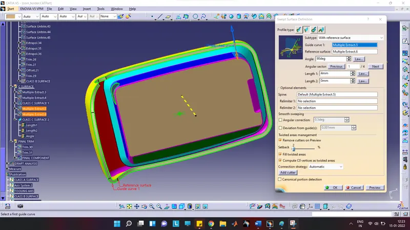
figure 02: - Use of tooling axis in catia (C surface)
The steps involved in creating tooling axis using the bisecting method are as follow: -
- Check continuity or quality of Class A surface
- Selection of best possible tooling direction
- Creating dummy tooling axis
- Tooling clearance for respective directions
- Creating final tooling axis
step1: - Check continuity or quality of Class A surface
Product designers should check the continuity or quality of the class A surface given by the class A engineer. They should ensure that there are no gaps between the surfaces using the boundary or the join command in catia.
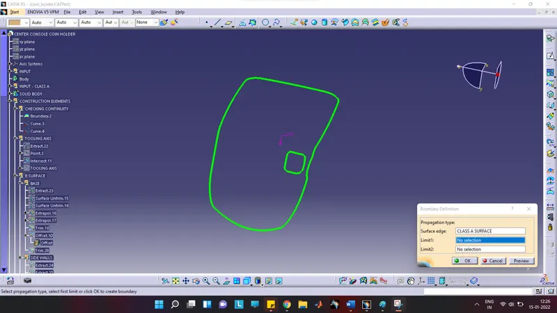
figure 03: - Checking the continuity (using boundary command)
step2: - Selection of best possible tooling direction
The tooling direction should be in such a way that it should cover the complete component along with its holes, undercuts, etc. in the main tooling. The product designer should also avoid side cores because the side cores generally increase the manufacturing cost of the component.
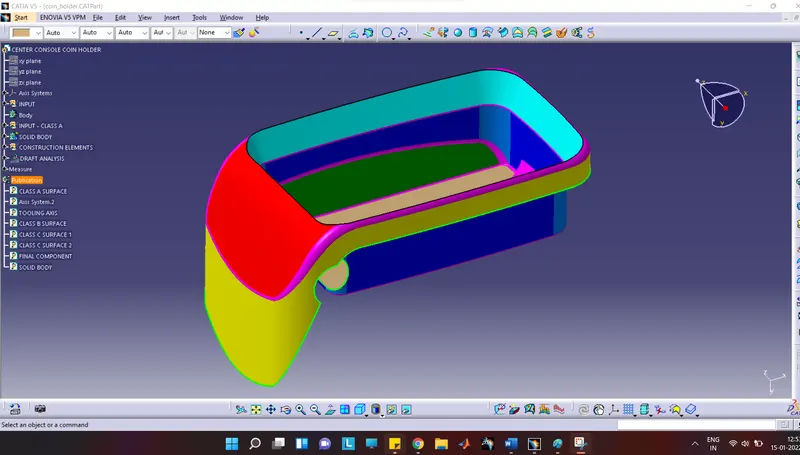
figure 04: - Coin Holder Model
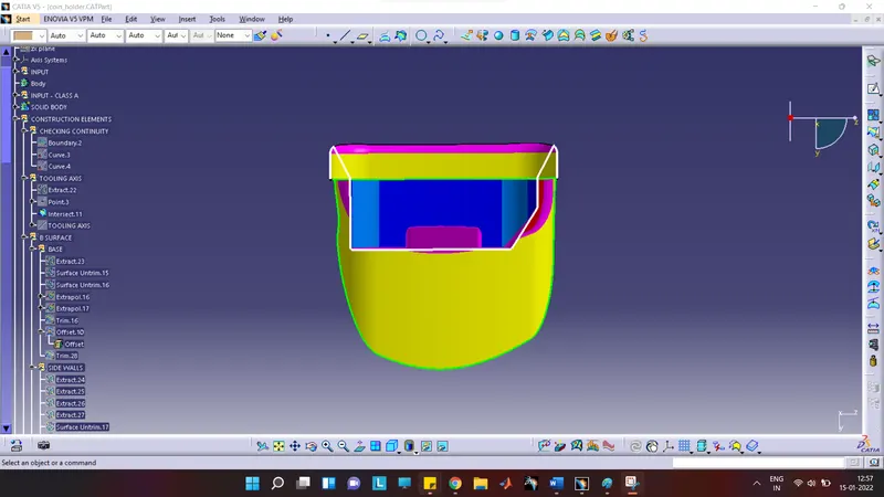
figure 05: - x-direction
After checking all the directions of the model shown in figure 04, it is found that most of the faces in the model are without a draft like shown in figure 05. Hence, the manufacturing of such components is impossible. A product designer should immediately concern the Class A engineer for such cases.
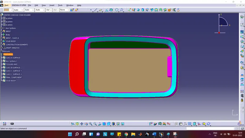
figure 06: - y-direction
Just for time being in order to continue the design further for creating the final component out of the surface model, one can select the y-direction as a tooling direction as shown in figure 06.
step3: - Creating dummy tooling axis
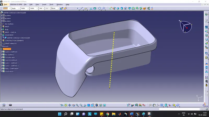
The dummy tooling axis is a line or an axis created at the center along the y-direction as shown in figure 07. The dummy tooling axis is used just as a reference and it is not the real tooling axis.
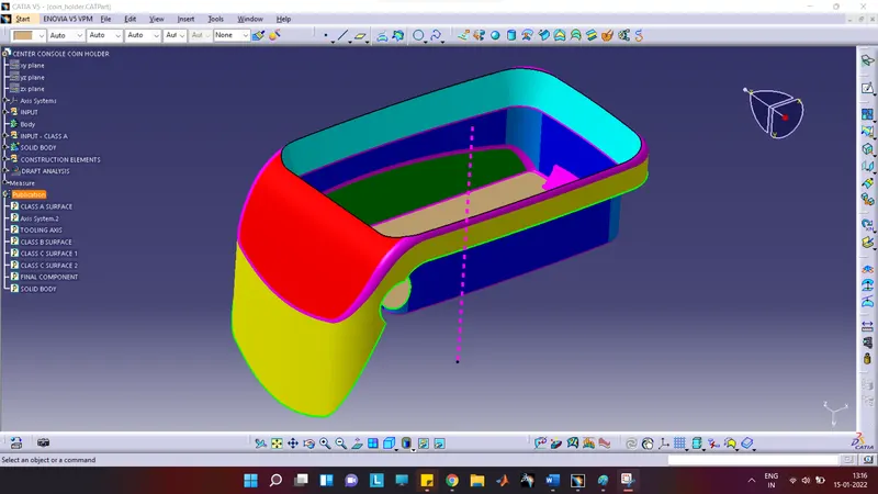
figure 07: - Dummy tooling axis
step4: - Tooling clearance for respective directions
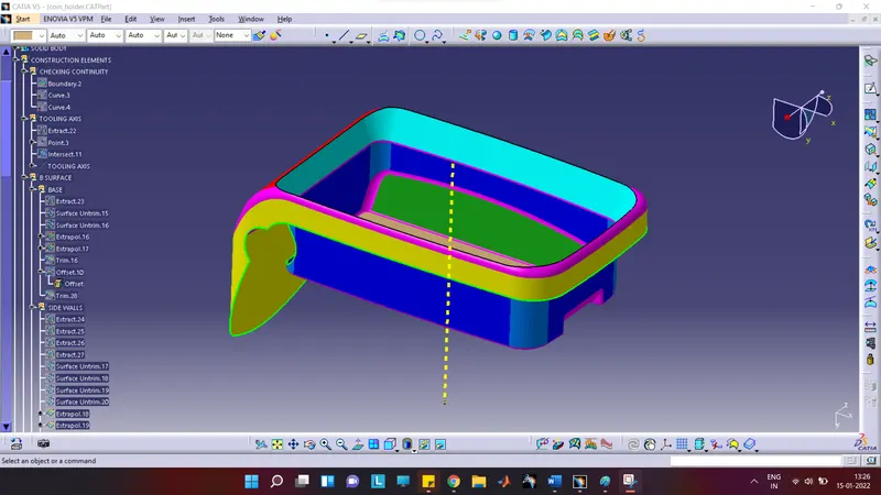
figure 08: - Main tooling axis
This step is skipped because we directly chose y-direction as our tooling direction as shown in figure 06 and made the tooling axis directly for the y-direction taking the center of the component as shown in figure 08. Basically, there is no involvement of bisecting method in this case.
- Publication: -
Using the publication option, the important parts of a model are easy to search.
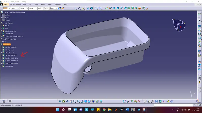
figure 09: - Coin Holder Model, Class A, B, and C and tooling axis are easy to search
3. Draft Analysis on Coin Holder Model: -
Draft: - Draft is providing angles or tapers on product features such as walls, ribs, posts, and bosses that lie parallel to the direction of release from the mold that eases the part ejection.
The draft is required on all parts in the direction of mold movement in order to allow parts to release or eject from the mold properly. The draft is the angle at which the part is tapered to allow it to release. As the part cools, it tends to shrink to the core side of the mold. Adding draft helps the part to release. 3 degrees is the nominal draft. Whereas, 0.5 degrees can also be manufactured at ribs. 7 degrees for the textured faces.
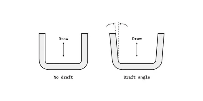
figure 10: - Example of draft
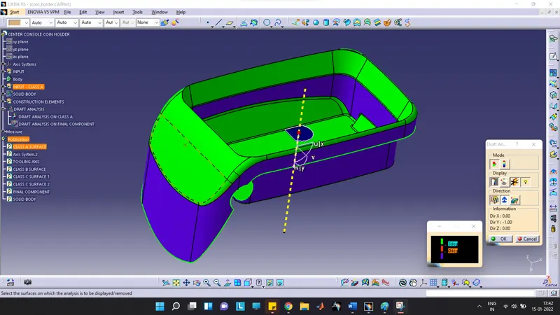
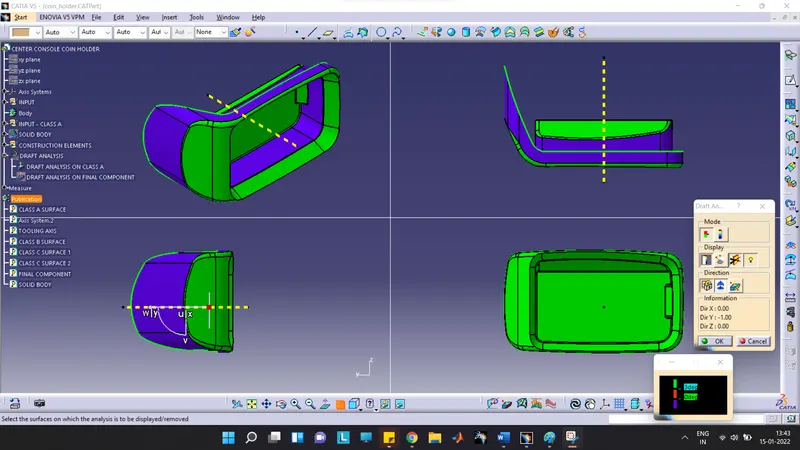
Draft analysis is used to confirm the appropriate draft angle required for the component that is to be manufactured. Quick analysis mode, show or hide color scale, and analysis under the running point are the three main features used in the draft analysis. The color scale shows the draft angle for different colored areas and the analysis under the running point shows the draft angle at different points.
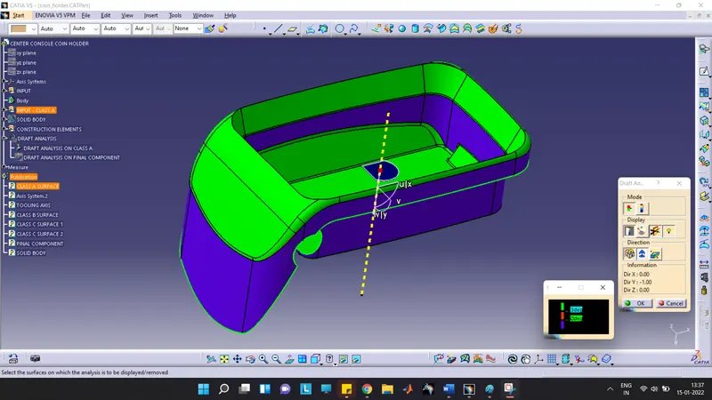
figure 11: - show or hide the color scale
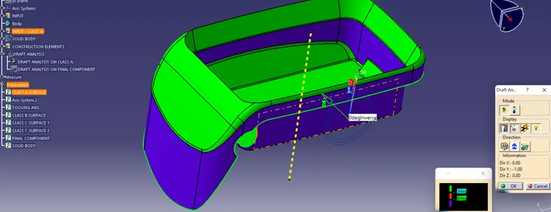
figure 12: - Analysis under the running point
Screenshots of the Draft analysis report: -
- Screenshots of the Draft analysis report for Class-A surface: -
- Image of the complete Draft analysis: -
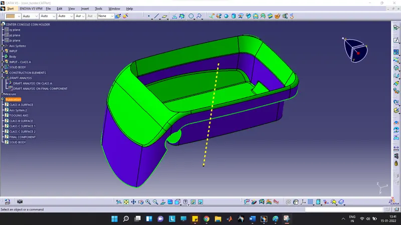
- Images of the color scale variant: -
- A model with the proper color code of the draft angle in various orientations (Isometric, Front, Side, and Top View): -
- Screenshots of the Draft analysis report for the final plastic component: -
- Image of the complete Draft analysis: -
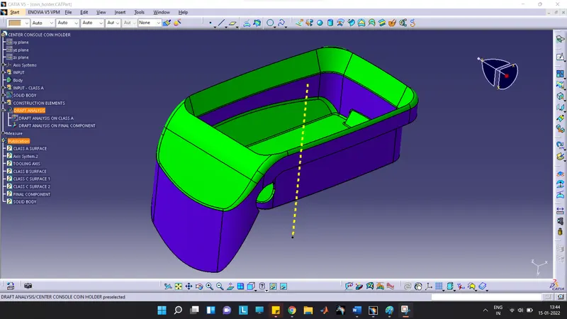
- Images of the color scale variant: -
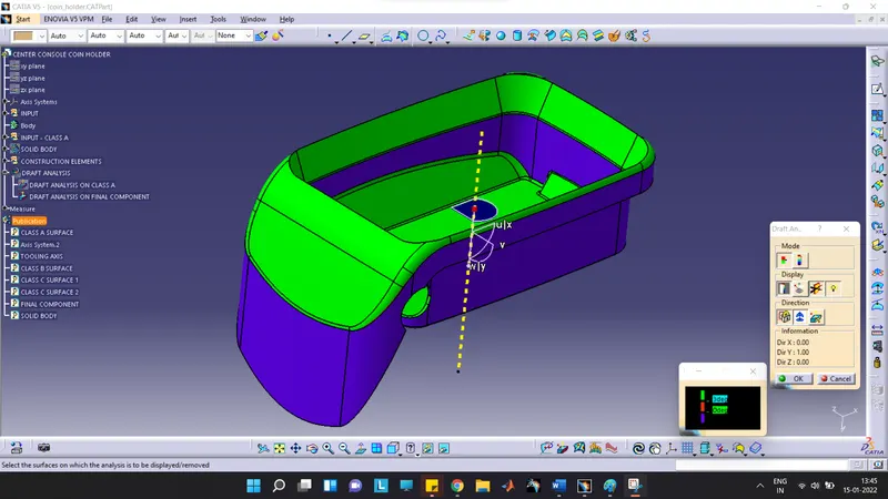
- A model with the proper color code of the draft angle in various orientations (Isometric, Front, Side, and Top View): -
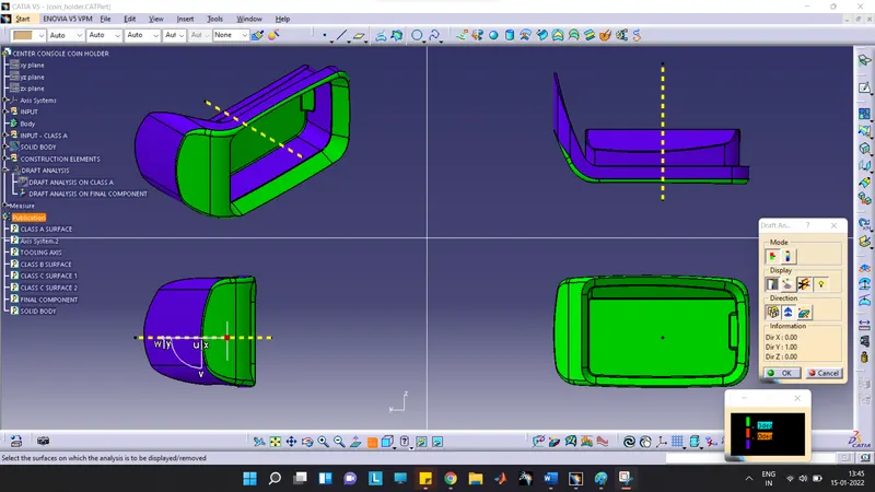
Other images: -
- Class A, B, and C surfaces: -
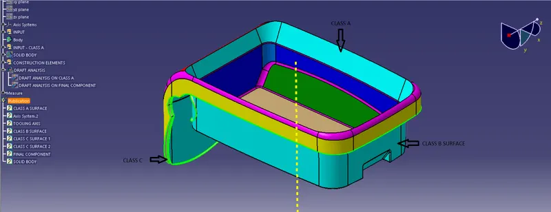
- Final plastic component (using the close surface feature): -
Conclusion: -
- Confirming the appropriate draft angle required for the component to be manufactured is one of the important aspects before continuing the design further.
- Adding a draft helps the part to release from the mold.
- The draft is important because it prevents damage from happening to the component while coming out of the mold.
- Ensuring a proper geometrical tree helps one to avoid confusion while re-editing a certain model.
- Using publication command while making a certain model is a boon while modifying or re-modifying it because things become handy.