Week 8 - Challenge 4 - Coin Holder Design
DESIGN OF COIN HOLDER
OBJECTIVE
To create coin holder plastic component from the given class- A surface.
To create the tooling axis for the plastic component
To perform draft analysis over the plastic component.
CLASS- A SURAFCE
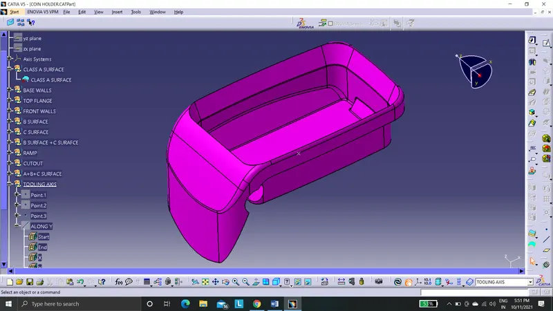
This is the given class- A surface. In which there base surface. Wall surface, hole feature and emboss feature.
GENERATING TOOLING AXIS
1. Boundry check the class A surface.
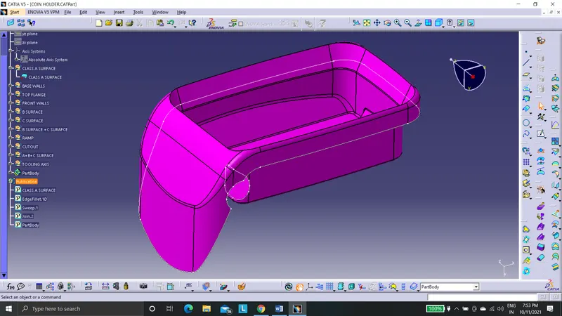
2. Plot the point in the class A surface.
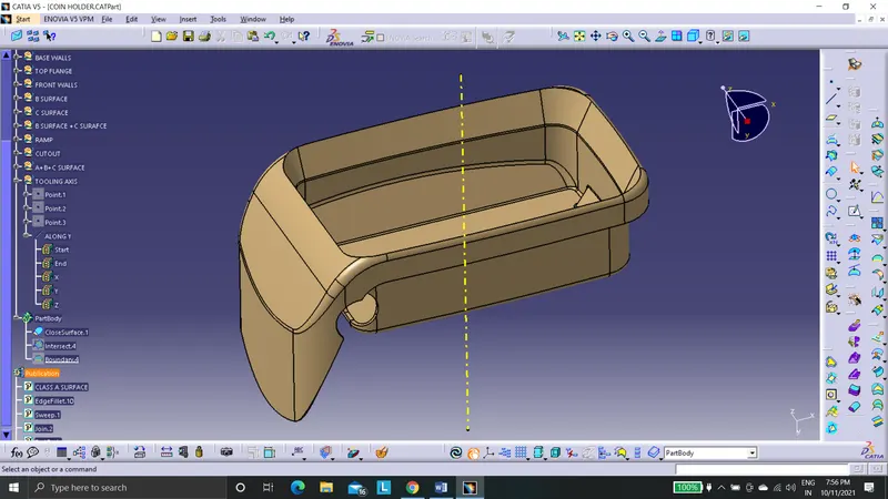
3. Add the axis system in the point mentioned.
4. Make a line in the direction along Y- axis.
COIN HOLDER DESIGN PROCEDURE
CLASS-B SURFACE
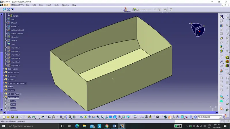
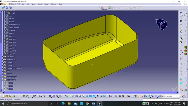
BASE WALL CREATION
- Bringing in the class-A surface.
- Extracting the wall surfaces.
- Un-trim the extracted surfaces.
- Extrapolate the un-trimmed surfaces.
- Trim the surface as per required shape.
- Offset the created rib surfaces for 2.5mm.
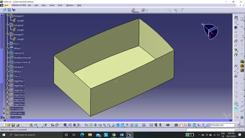
- Now side steep feature has to be added to the main base surface.
- Extract the steep surface from class A surface.
- Surface untrim it.
- Extrapolate and offset for 2.5mm.
- Trim it with base surface.
- Apply fillet edges command to all edges.
- Fillet value will be increased by 2.5mm.
CREATION OF TOP WALL SURFACE
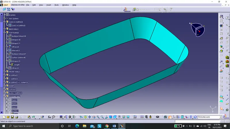
- Extract the surface from class-A surface.
- Un-trim the base surface.
- Extrapolate the base surface.
- Offset the base surface for 2.5mm
CREATION OF FRONT WALL SURFACE
- Extract the surface from class-A surface.
- Un-trim the surfaces.
- Extrapolate the surfaces.
- Offset the base surface for 2.5mm.
- Trim them together which forms a front wall surfaces.
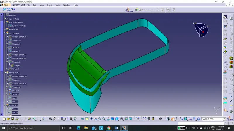
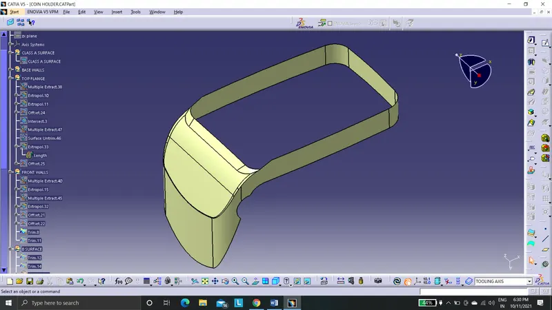
6. Now trim, the front wall surfaces with the top wall surface which is already created.
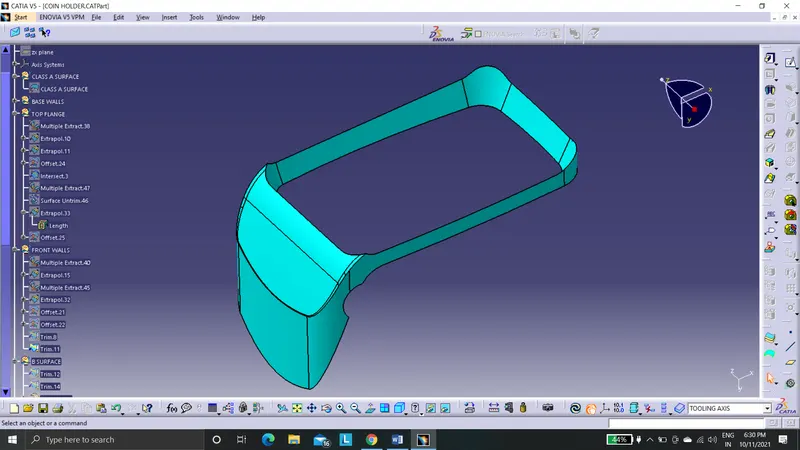
7. Since the class-B surface is 2.5mm downwards to the class-A surface need to subtract this offset distance with the filleting radius observed from the class-A surface.
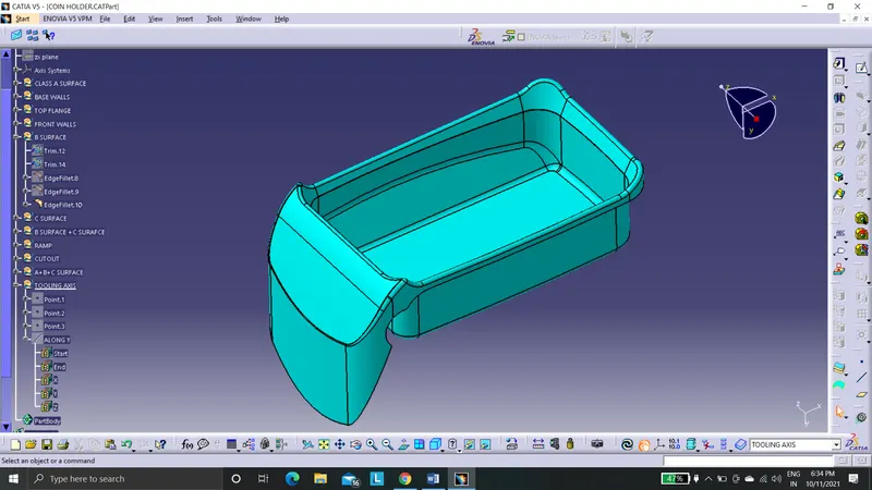
CLASS-C SURFACE
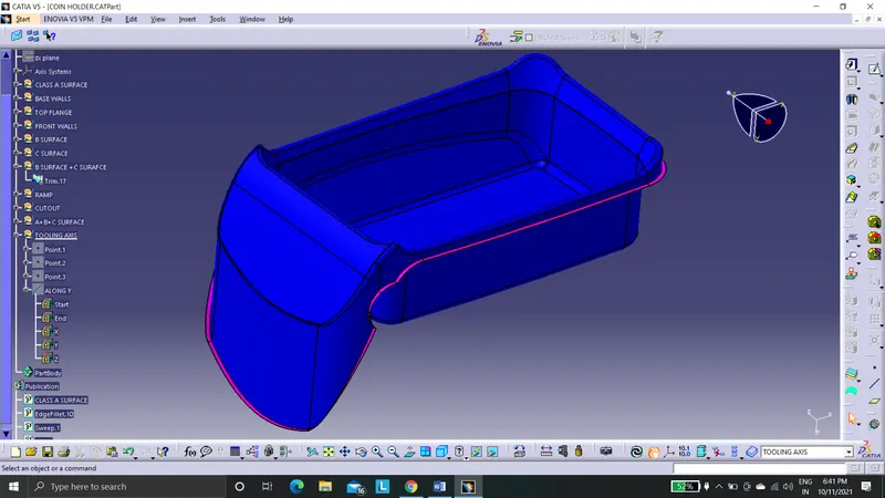
This the connecting surface of class-A and class-B surfaces.
- Create the boundary of class-A surface using boundary command.
- Smoothen the boundary curve generated because it is already noted that the boundary curve is discontinuous.
- Use sweep command to generate class-C surface using with reference to the surface at 90 degrees.
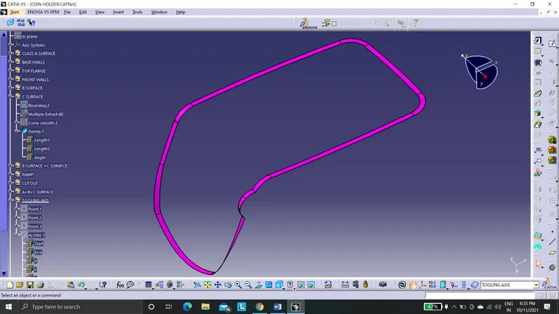
4. Trim the class C surface with the class B surface which is already created.
EMBOSS CREATION
- Extract the surface from class-A surface.
- Un-trim the surfaces.
- Extrapolate the surfaces.
- Offset the base surface for 2.5mm.
- Trim them together which forms emboss surfaces.
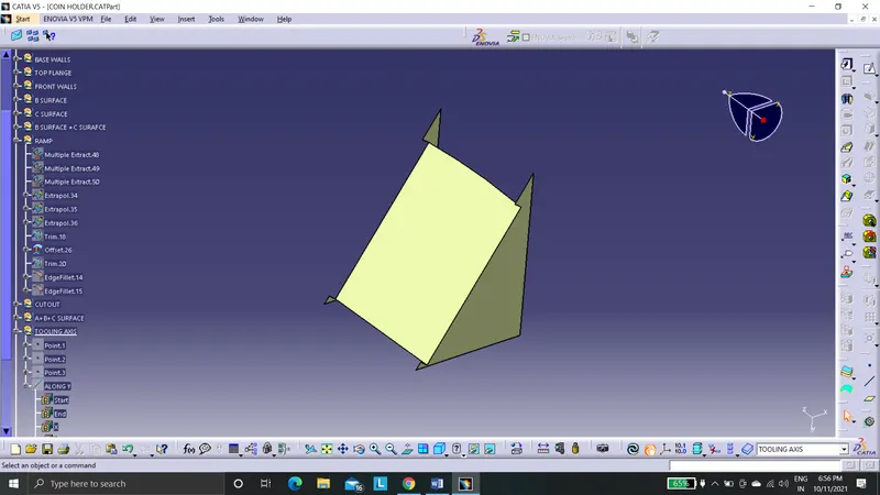
6. Trim the emboss surfaces with the class B surface already created.
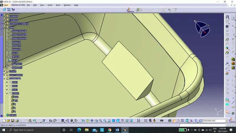
7. Apply fillet edges, where the minimum fillet is 0.5mm.
CUTOUT
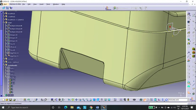
- Create the boundary of class-A surface using boundary command.
- Smoothen the boundary curve generated because it is already noted that the boundary curve is discontinuous.
- Use sweep command to generate class-C surface using with reference to the surface at 90 degrees.
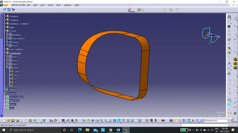
4. Trim the sweep surface with the class B surface.
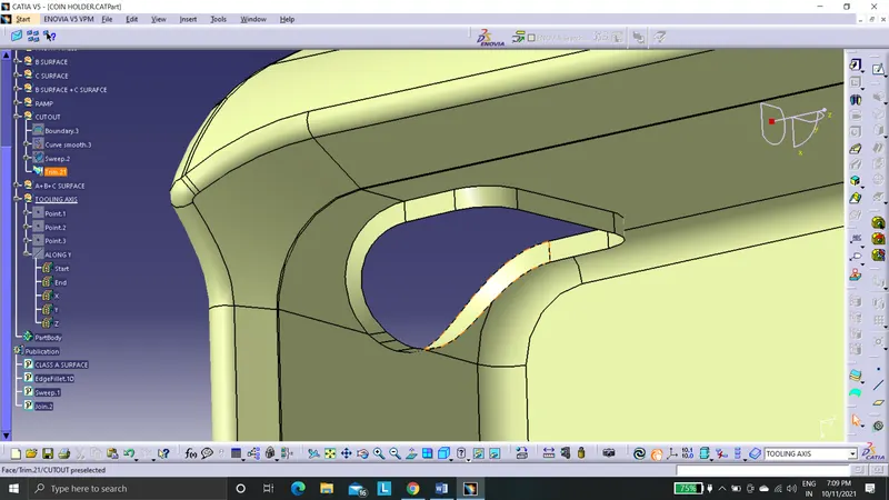
JOIN
- Join the class A, class B and class C surfaces.
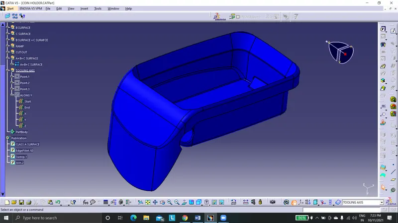
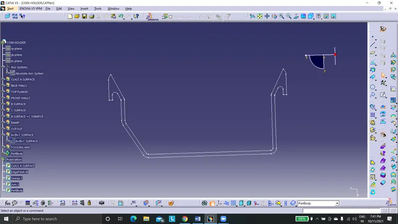
CLOSED SURFACE
- Publish class-A, class-B, class-C surfaces and tooling axis.
- Join all the surface together.
- Create closed surface.

DRAFT ANALYSIS
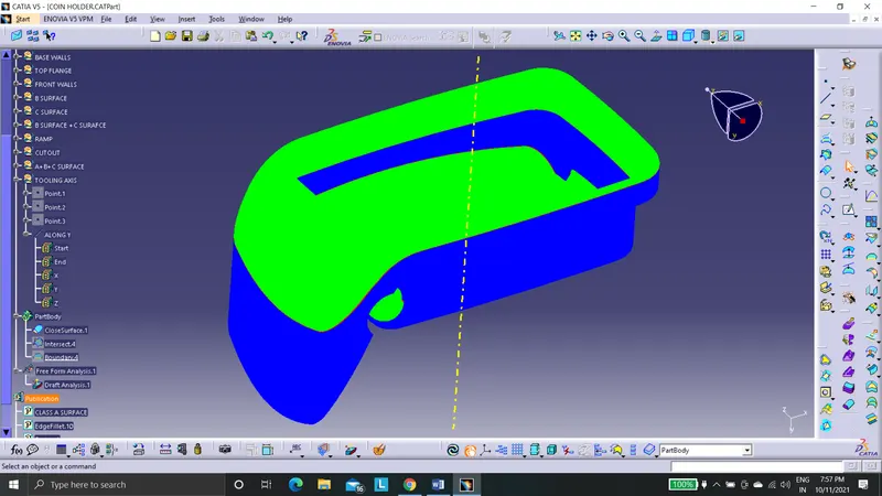
From draft analysis we can conclude that the side walls are at exactly perpendicular to base surface. so we cannot manufacture a plastic componenet without nominal draft angle. Therefore there has to be some changes need to be made in the class A surface.