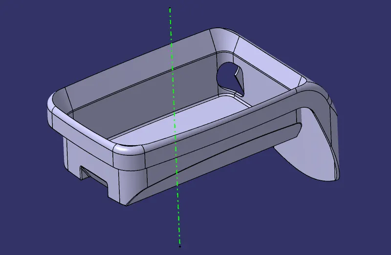
Coin Holder Design
COIN HOLDER DESIGN
CREATING TOOLING AXIS:
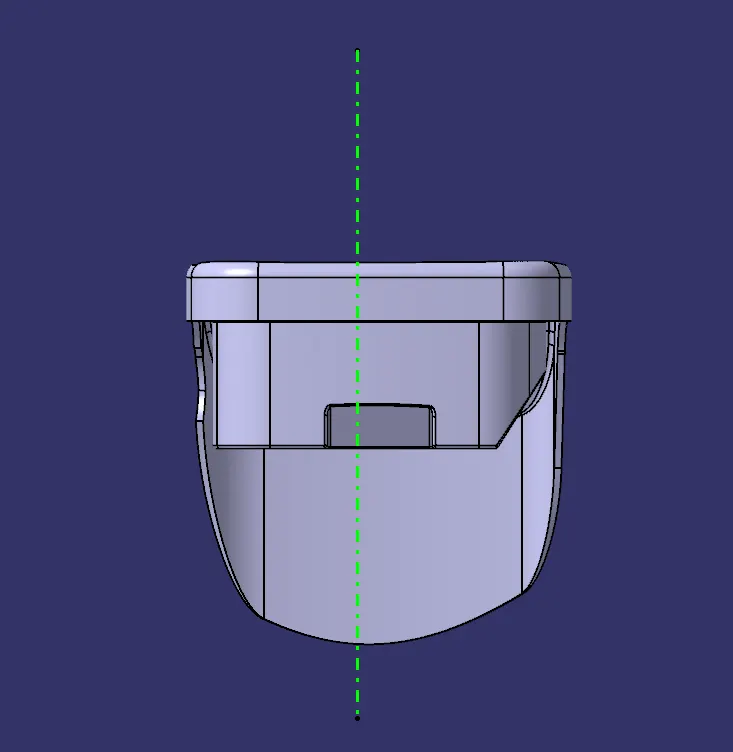
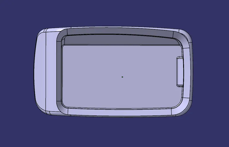
- For obtaining the tooling direction, we will consider all the 3 axes and view the part along them.
- We extract the bottom hole edge, use fill surface to fill the hole and take a point at its center.
- After viewing the part in different views, we can conclude that direction along Y axis is appropriate for our tooling axis.
- For the tooling direction, we extract the base surface and take a point at the center of the extracted surface. Then we take an axis system at the point as origin and axes direction similar to the system axes.
- When we take intersection along YZ plane of the axis system as shown below, we can see that all the lines along vertical direction in the intersection are at some distance but at 0-degree angle with Y axis. This means they are actually vertical.
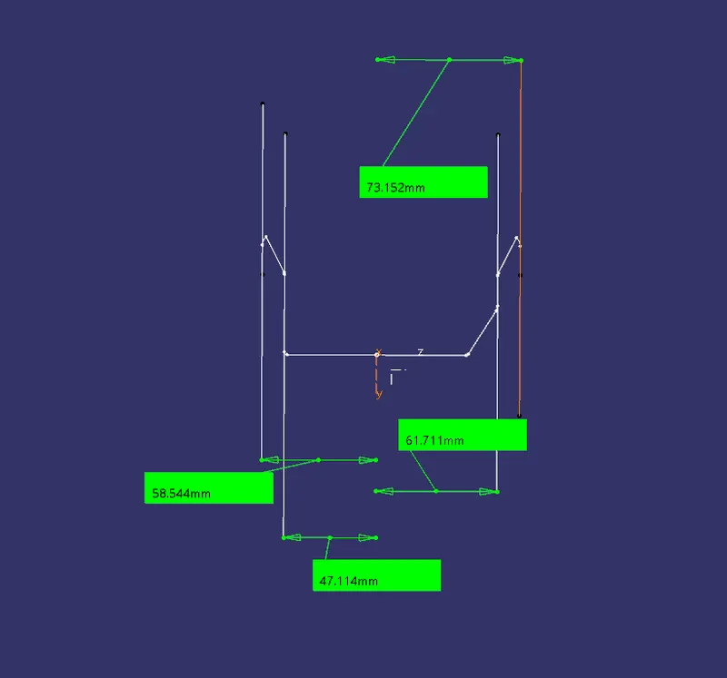
- Hence it is suggested that Class A surface may be modified to have some draft for these vertical surfaces.
- Moving further for the tooling direction, we take a line passing through the previous point and along Y direction. This is our main tooling direction for this case.
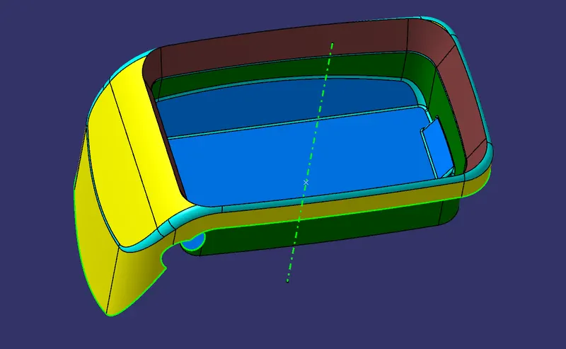
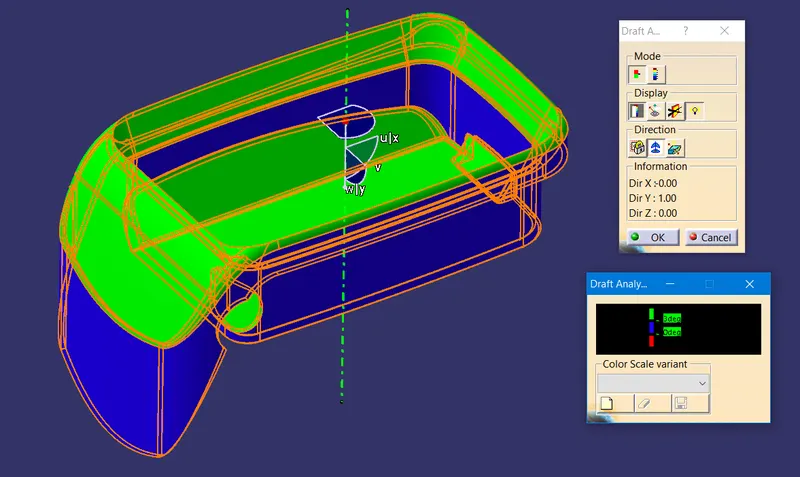
- In the draft analysis results ahead, it should be noted that some sections of the draft are in blue, meaning draft angle between 0 to 3 degrees. This is because the blues surfaces are along vertical direction and have not been provided any draft angle.
IMAGES
DRAFT ANALYSIS AND COLOR SCALE VARIANT
Class A Surface
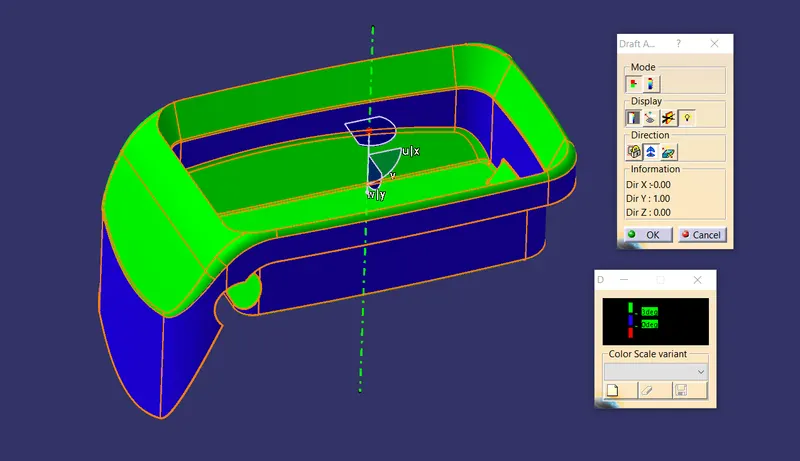
Solid Body
Model different views
Surface Body
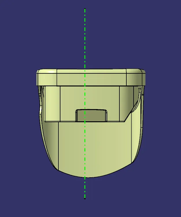
Front view
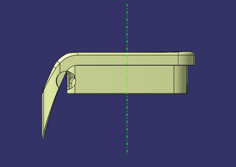
Side view
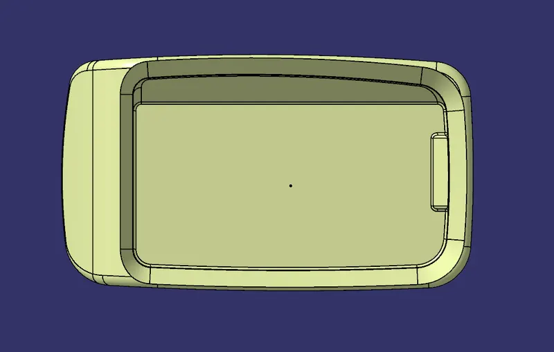
Top view
Isometric view
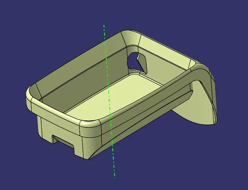
Solid Body
Front view
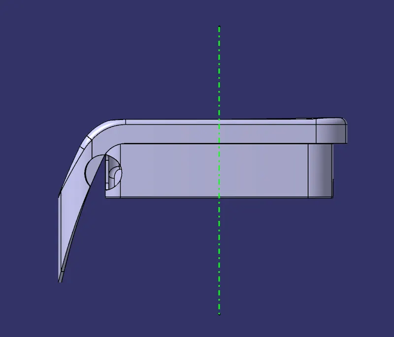
Side view
Top view
Isometric view