Week 8 - Challenge 4 - Coin Holder Design
COIN HOLDER
Aim:
To design a Coin Holder from the given class A surface
Procedure:
Check for connectivity:
The given class A surface is checked for connectivity inorder to ensure that there is no gap between the surfaces if the gaps are present and then it shoul reslved.The connectivity is checked using joint and boundary tools in catia.
Tooling direction:
Tooling direction indicates the direction at which core contacts the cavity.
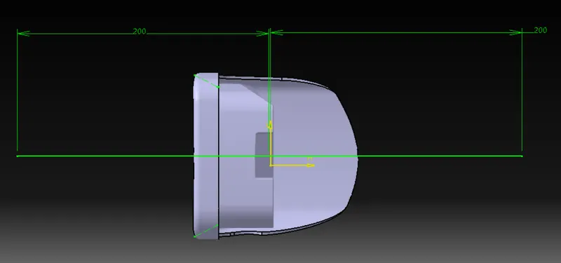
Here the tooling direction is taken by taking intersection between axis and surface and then taking bisecting line between the side walls of the part.
Draft analysis:
Draft is providing angle or tapers on product features such as wall ribs,posts or bosses that lie parallel to the direction of release from the mold eases part ejection.
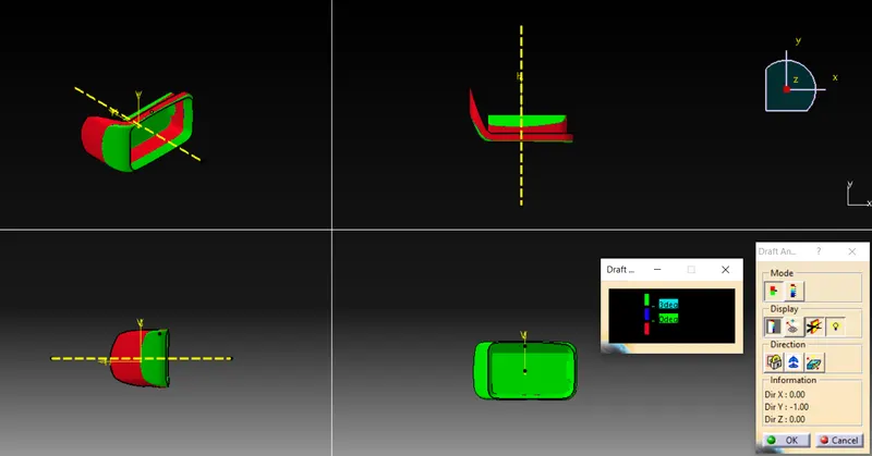
The Draft Analysis command enables you to detect if the part you drafted will be easily removed.Draft analysis is performed based on color ranges identifying zones on the analysed element where the deviation from the draft direction at any point corresponds to specified values.Draft is required on all parts in the direction of mold movement in order to allow parts to realease or eject from the mold properly.
Draft analysis of class A surface:
Creating class B surface:
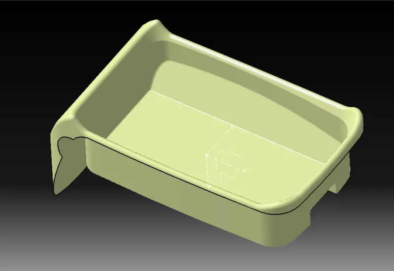
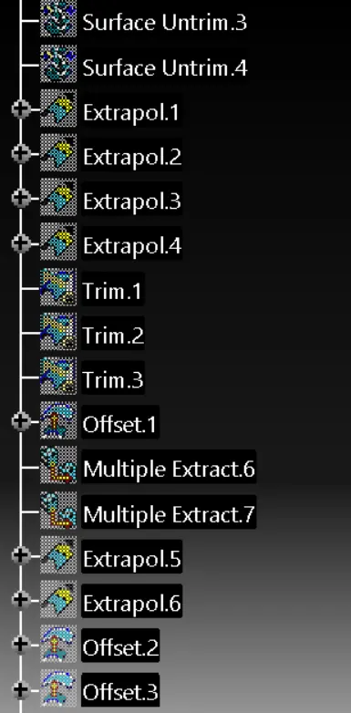
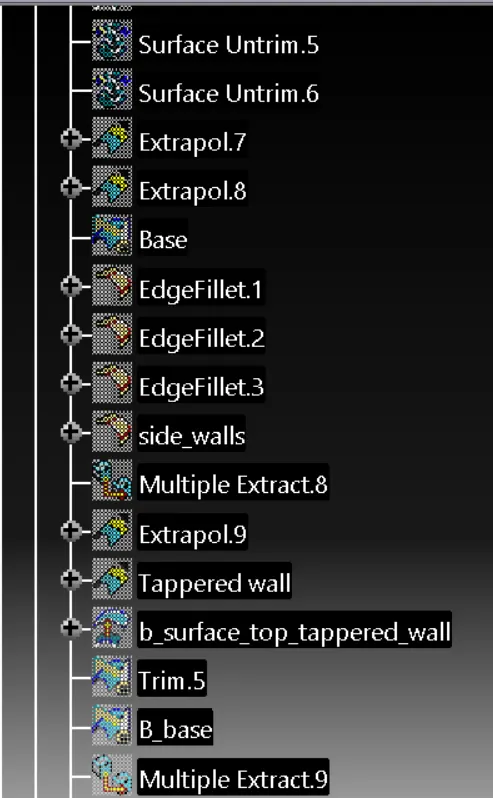
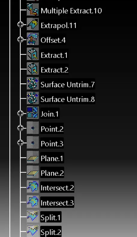
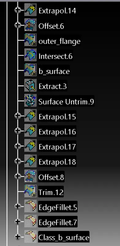
Class B surface is is created from the given class A surface using extract,untrim,extrapolate,trim,offset tools available in catia.
Creating class C surfaces:
- Class C surfaces is created to joint class A and class B surface.It is created using sweep command(sweep with referance surface) and also giving an angle of 90 deg
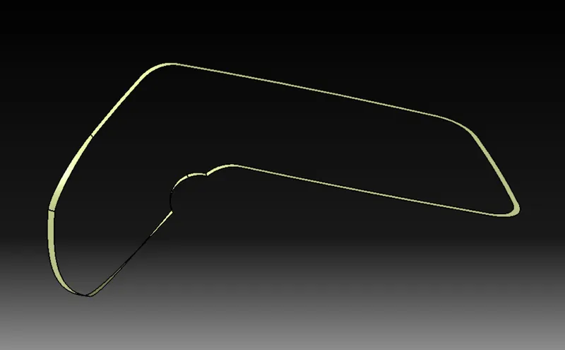
- The outer boundary of the class A is taken using boundary and swept to create class C surface in required direction.
Final output:
After creating surface C the surface A and surface C is jointed and then it is trimed using surface B.
After getting required shape the surface is thicken using closed surface tool.
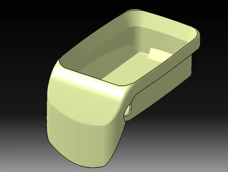
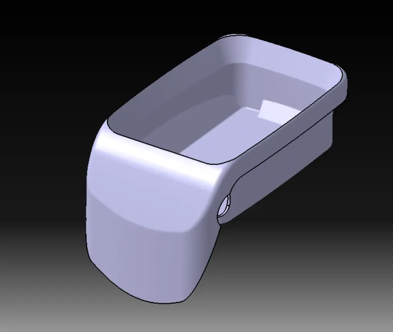
Isometric view:
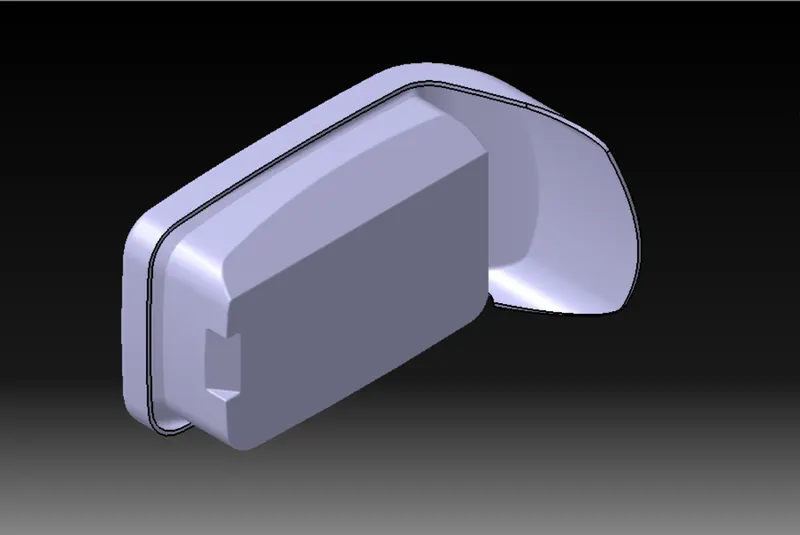
Front view:
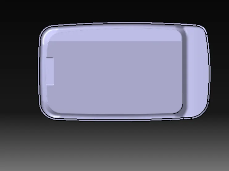
Top view:
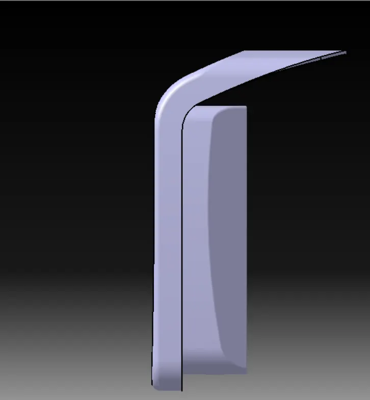
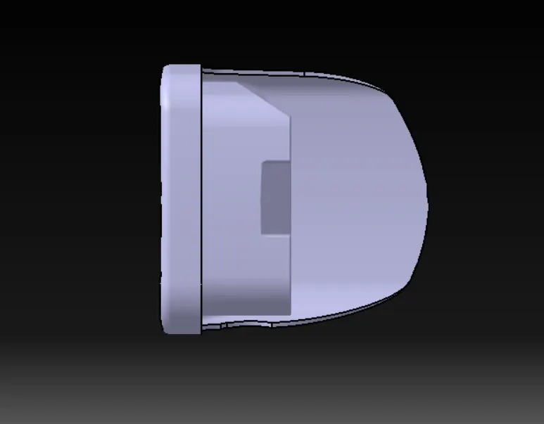
Side view:
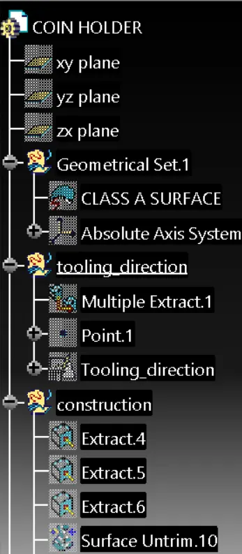
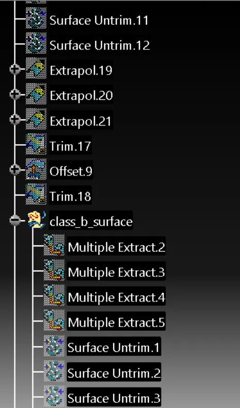
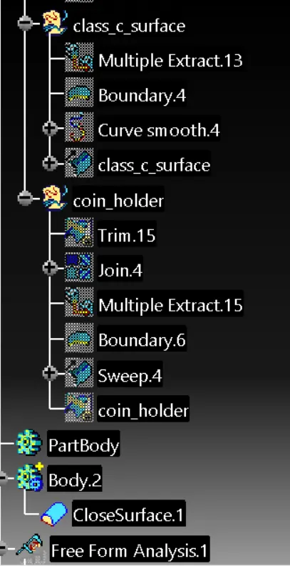
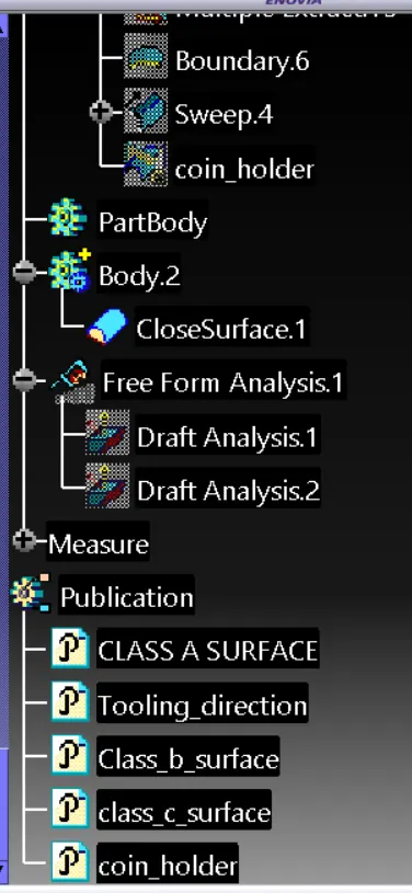
Geomrtric set:
Draft analysis report:
Draft analysis of class A surface
Draft analysis of solid part:
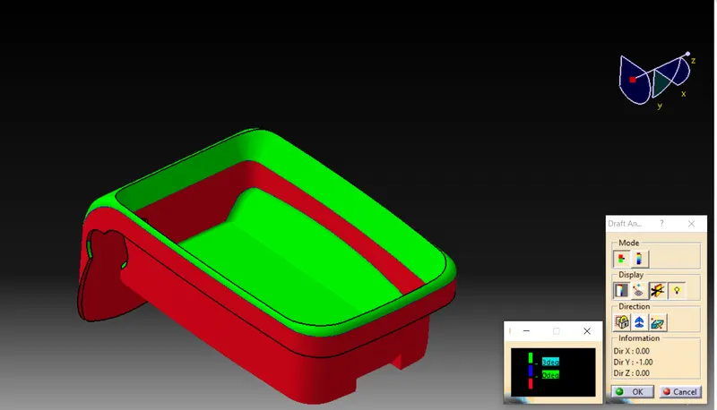
The green colour indicates the draft angle 3deg and above
The blue colour indicated draft angle between 0-3 deg
The red colour indicates negative draft.
Since we have negative draft it should be provided with required draft by the styling team inorder to avoid faliure during manufacturing process.