Week 8 - Challenge 4 - Bumper
AIM :
To create a Solid body of Bumper from the input Class A-surface of a Bumper. The created body should be a closed solid volume which should be feasible for manufacturing and Tooling. The draft angle and draft analysis of the component should be done.
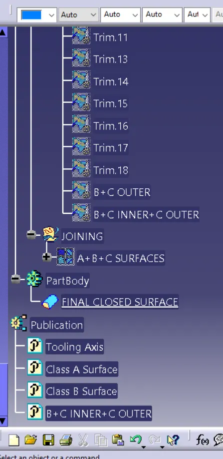
In model, proper tree structure to be maintained and publications of Tooling axis,A,B and C surfaces to be done.
INPUT GIVEN:
A-Surface
Thickness of component is 3.00mm
Draft angle is 3 degrees.
CHECKING THE INPUT - A SURFACE:
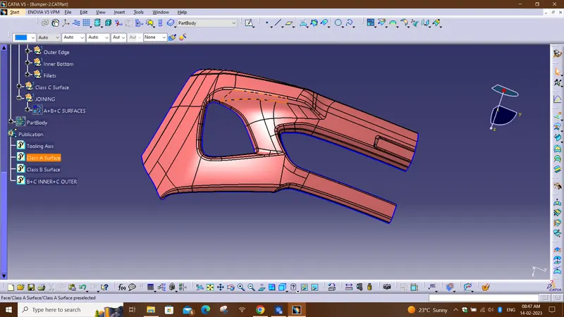
The A-surface or the styling surface is first checked for any gaps and other issues in its surfaces. This Surface acts as the input surface so any correction to be done should be with approval from the styling team or done by them. A- perfect surface is the one when a boundary is created, the lines are only on the edges of a component and its holes or cutouts as shown below.
TOOLING AXIS:
Tooling axis represents the opening and closing of the mold core and cavity during the manufacturing of the components. A plastic product designer should consider the best tooling direction to cutdown the cost of the component very less.
Method opted for creating tooling axis for the bumper
- Check the best tooling direction for the given surface.
- In this model we cheked for the flat surface, Extracted it and Used NORMAL TO SURFACE mehod.
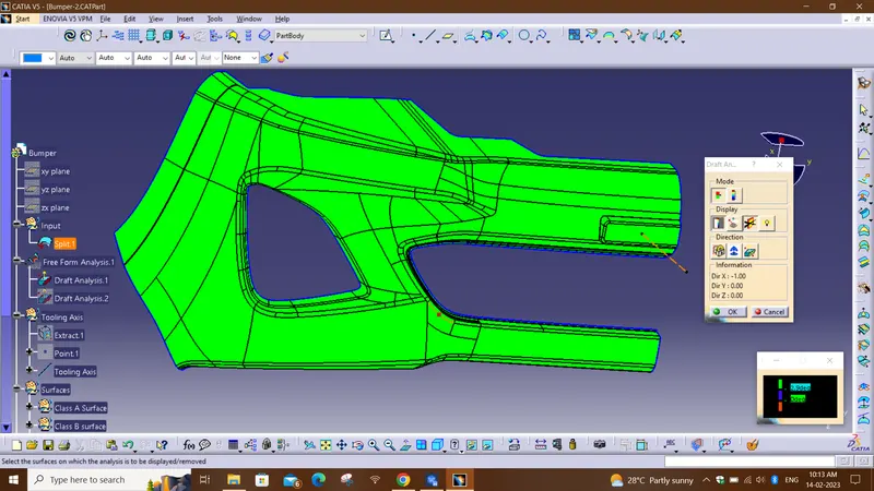
- Then we performed Draft analysis using the tooling axis and Class A Surface passed.
Given Class A Surface-
Draft Analysis of Class-A surface :-
Class B Surface Creation-
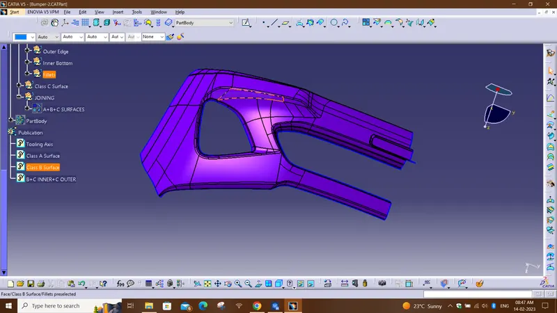
Class-B surface means thickness of a part it is not visible and is inside part. In other words, Class-B surface is a surface below a certain thickness from the class-A surface. This is the surface that contains engineering aspects of a model.
- Offset the class-A surface to 3mm inward direction.
- Rework on the patches and discontinuity of the offset surfaces using the features like extract, multi-extract, sweep, multi-section surfaces, extrapolate.
- To ensure the continuity of the Class-B surfaces check the boundary command to find out the boundary.
- Hence class-B surface creation is done.
Class C Surface Creation-
Surface that joins class-A and class-B surfaces is class-C surface. Class C is often specified for interior surfaces not readily visible, surfaces that will be covered by another part when assembled.
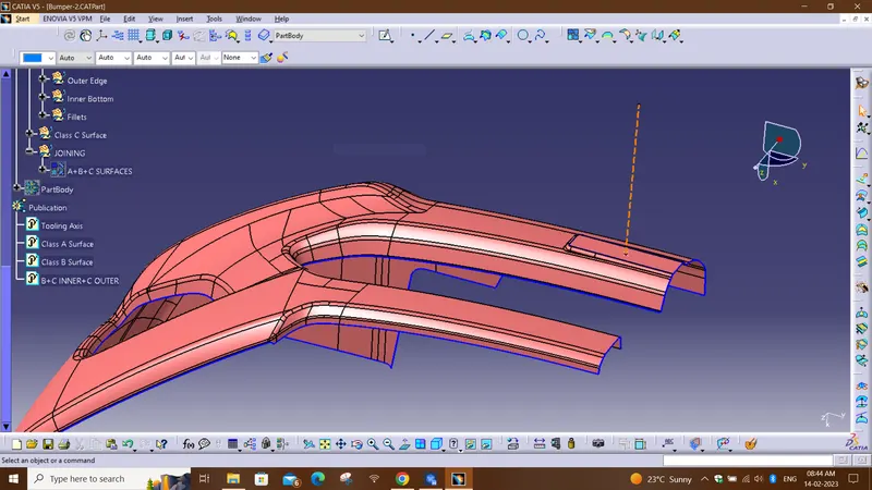
Since it is a complex class-A surface, we cannot simply create the class-A boundary curve and sweep it at one shot. Hence, we need to create smaller curves using multi-extract command and then create sweep of 90 degree with reference to the surface option. sweeps at the midportion of the bumper should have a 86 degree vaue to pass the draft analysis.
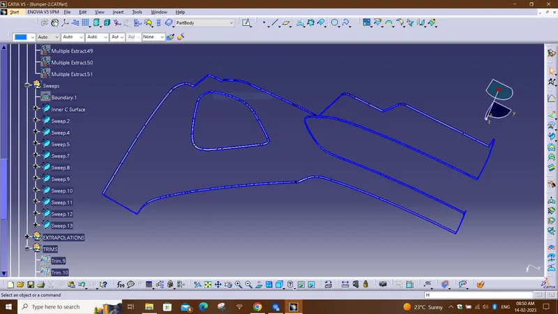
- In This model I am not able to create the outer class c model de to self intersection error.
- So, I have to Individually Extrapolate patch by patch.
- Then sweep the extracts individually.
- Using Trim Option with Class B surface I have to join sweep part by part.
CLASS B+CLASS C OUTER
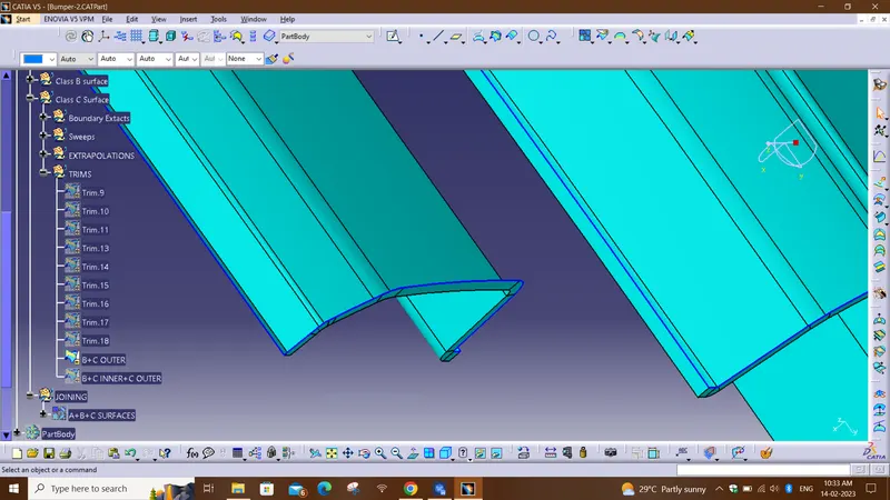
- Then joined Class B surface, Outer C Surface and Inner C surface Using Trim.
CLASS B+CLASS C OUTER+ CLASS C INNER
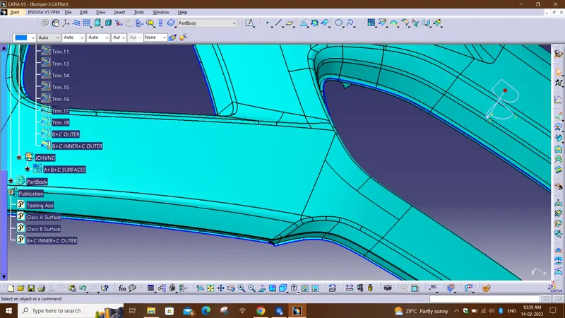
- Then By using JOIN command By joining class A surface and remaining surface formed A closed Surface.
CLOSED SURFACE OR A+B+C SURFACE:
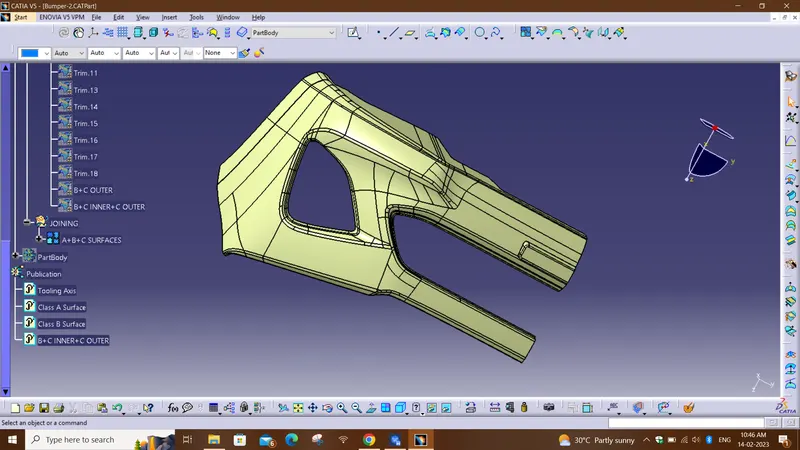
DIFFERENT VIEWS OF SOLID BODY:
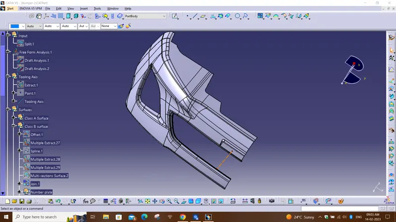
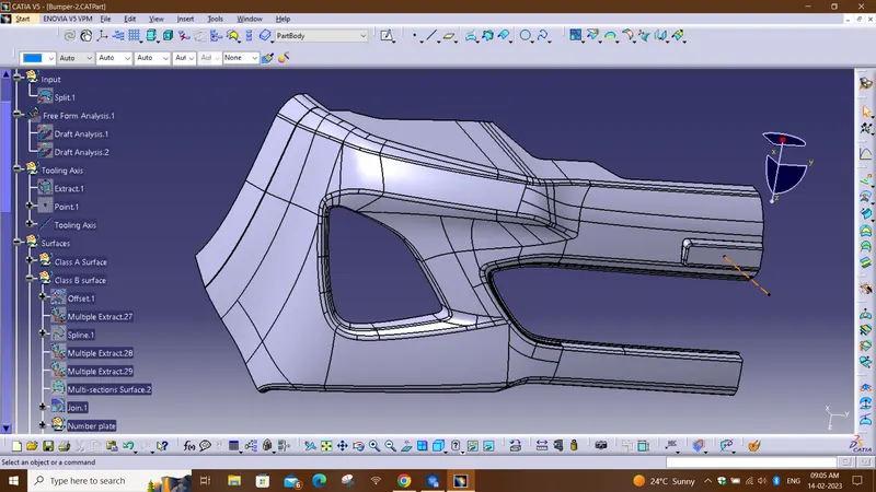
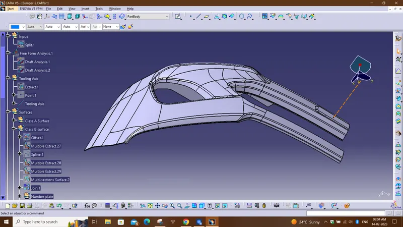
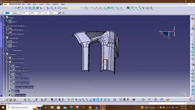
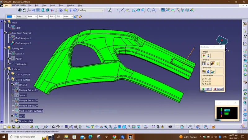
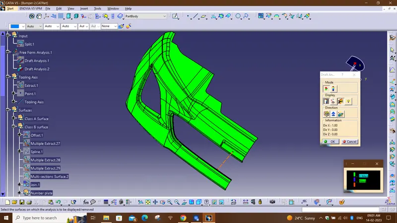
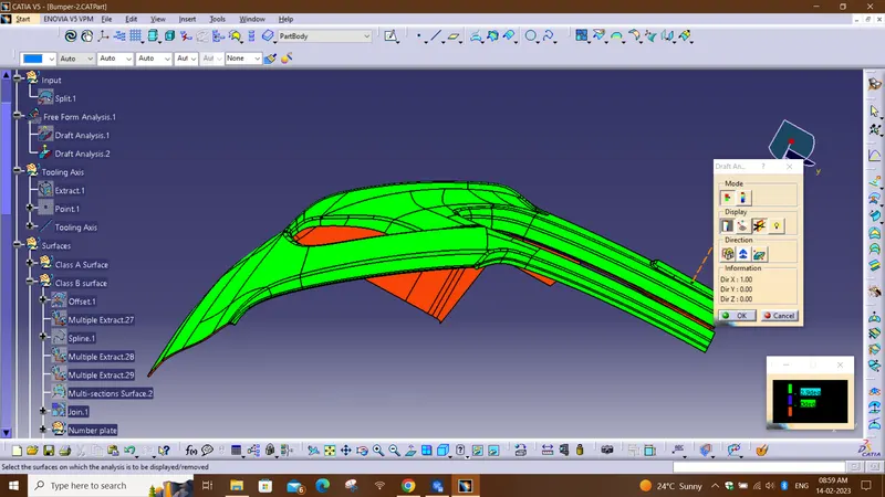
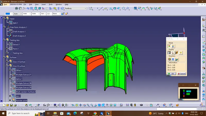
DIFFERENT DRAFT ANALYSIS VIEWS OF SOLID BODY:
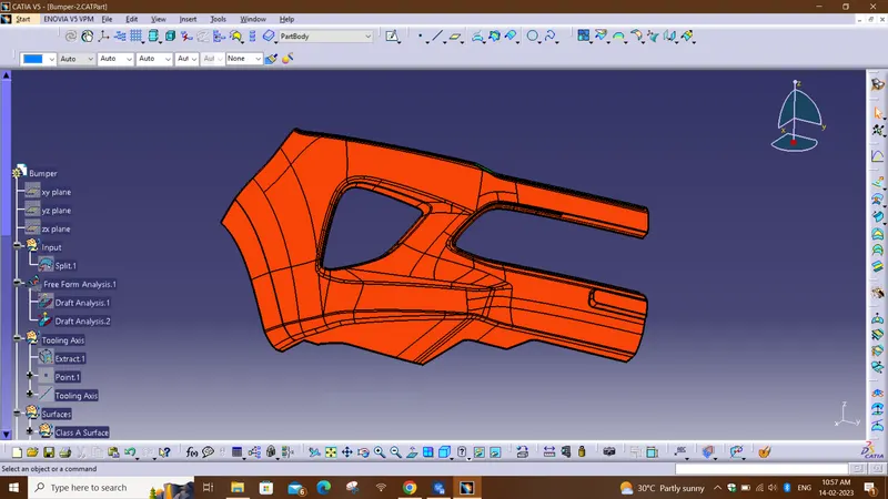
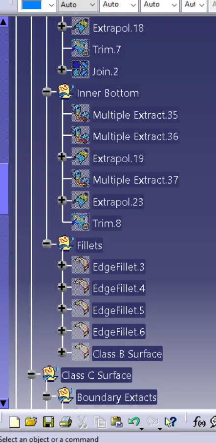
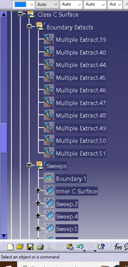
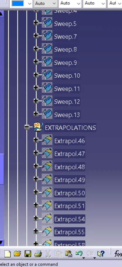
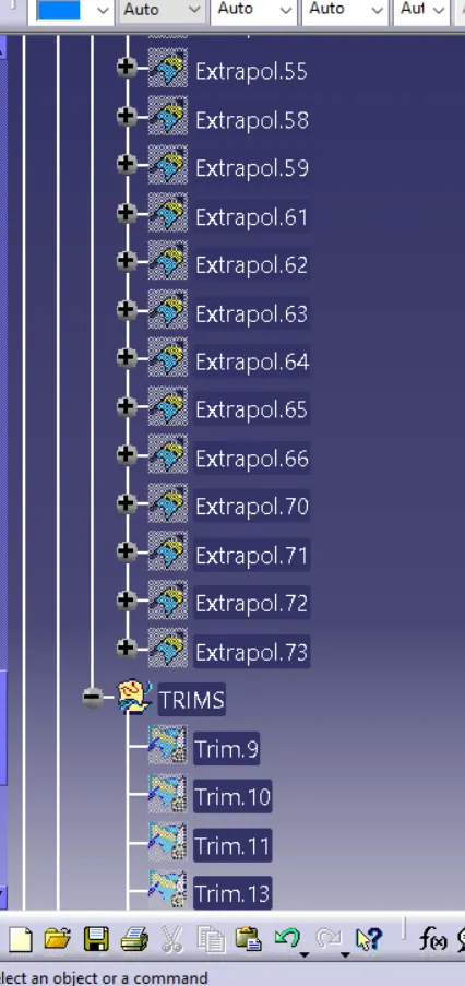
TREE STRUCTURE:
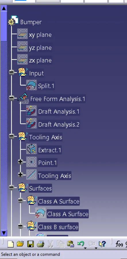
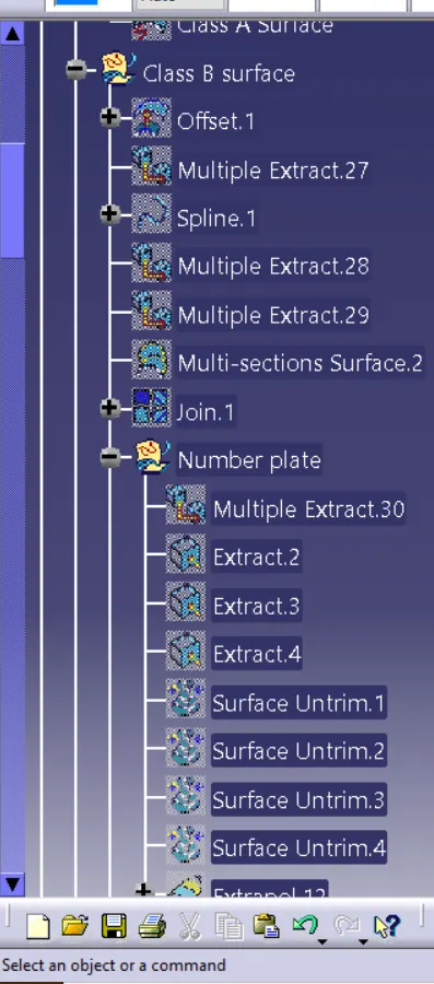
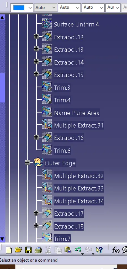
Conclusion
I have successfully created the class-B and Class-C surfaces of Bumper using the given Class-A surface along with the tooling axis in the CATIA surface workbench.