Week 8 - Challenge 4 - Bumper
Report on Creating the Bumper Plastic component through the given Class-A surface. With, the creation of the tooling axis for the given Class-A Surface for the draft angle requirements and the draft analysis performance on the solid model and the Class A.
Introduction:
A bumper is a structure attached to or built into the front and rear of a vehicle to absorb the impact of minor crashes and ideally minimize repair costs. Today's standard automobile bumpers have a stiff reinforcing bar under the outer cover and a compressible foam or plastic section underneath.
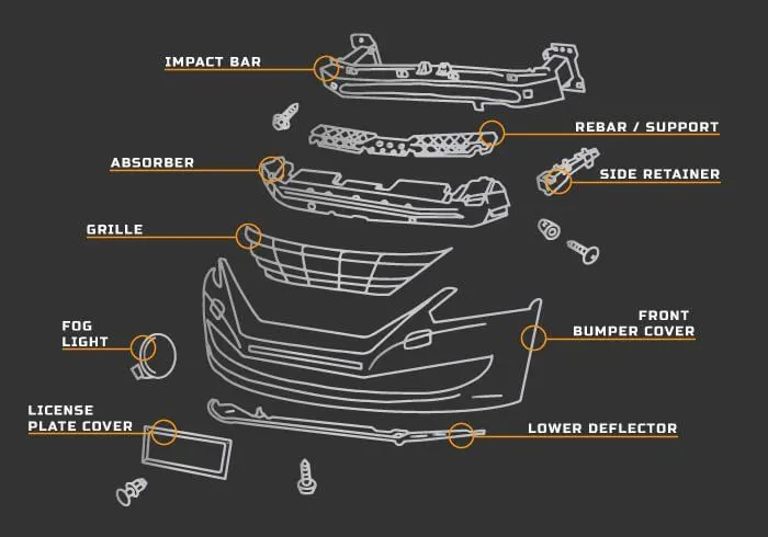
The input for the design is the Bumper cover here, the input given to the product designer is in the form of the A-class surface. The job of the product designer is to create the B and C surfaces keeping all the aspects of the mold.
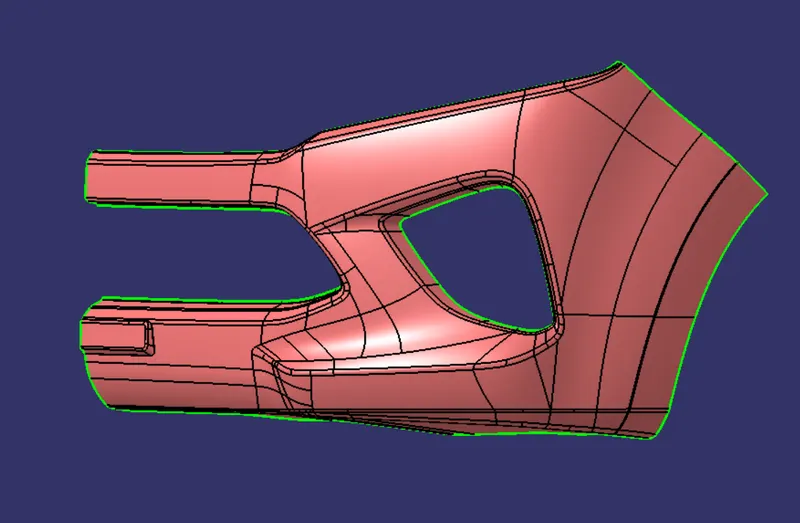
Class A is a visible surface and has that aesthetic look. Also might have the textures that are provided by the OEM. It does not have any features like(rib, snap, bosses, etc). And are made from scanned data with different software like alias etc.
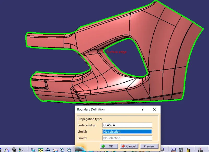
The first step is to check the continuity of the class A surface. This is to ensure that there is no gap between surfaces. If we find any then we should fix that first.
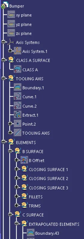
Next is to determine where the tooling axis should be formed. The tooling axis represents the opening and closing of the mold core and cavity during the manufacturing of the components. A plastic product designer should consider the best tooling direction to cut down the cost of the component very less.
To Check the best tooling direction for the given surface. We can find out the best tooling direction by checking all three axes. We can find out that the best tooling direction for the bumper class-A surface is along the x-axis direction method chosen to create the tooling axis is first extracting a flat surface and creating a midpoint on that surface. By introducing an axis system on that point. Then created the tooling axis with the point and direction along the x-axis.
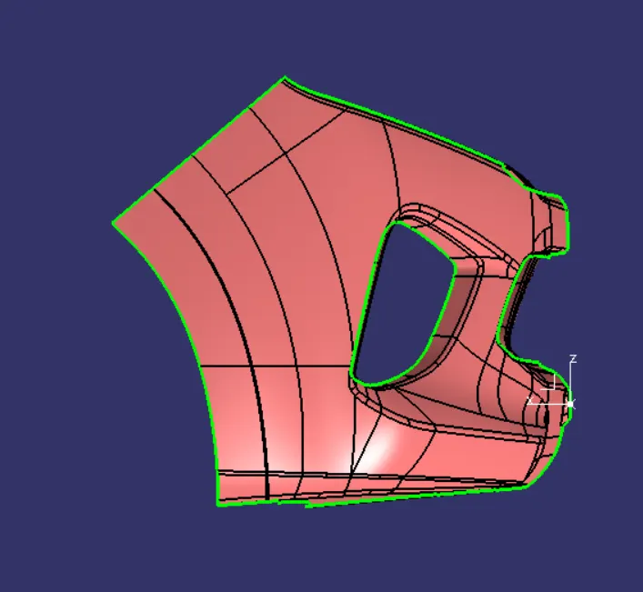
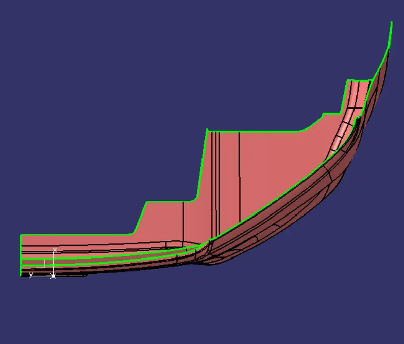
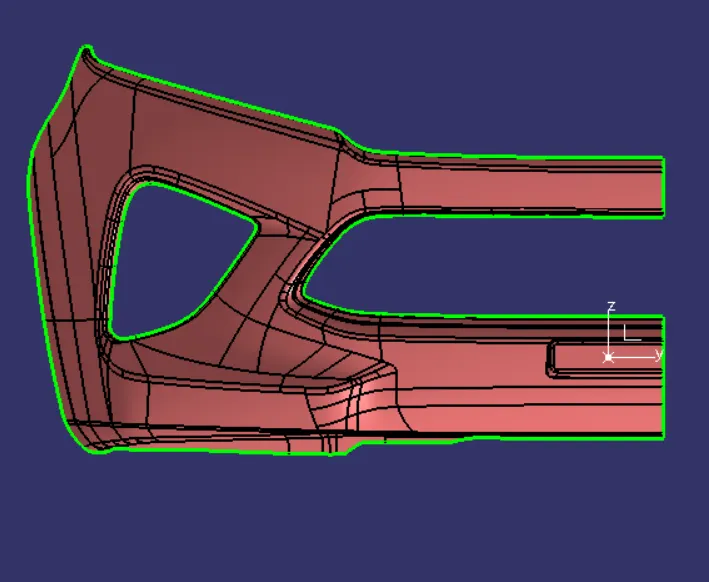
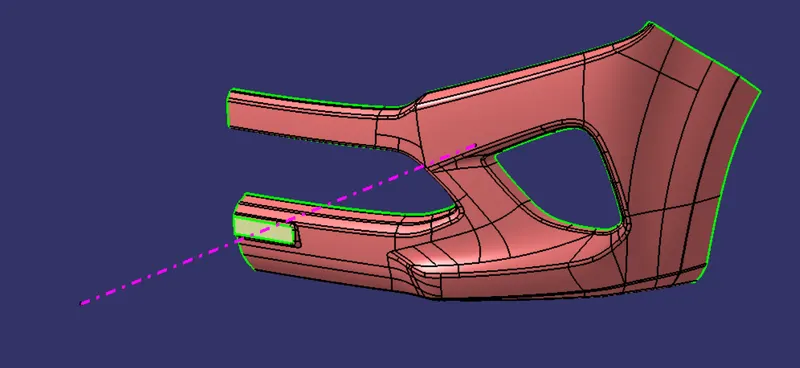
The method by which we can get a tooling axis is by using Bisecting method, to instigate the process similarly having a closed geometry such as a circle or flat surface which will be handy to create a dummy tooling axis, further using the intersection tool in the tool direction plane as a guide for the parallel geometries can be created and using the two of the line the axis can be created using the bisecting option which will be the actual tooling axis for the body to be manufactured in that direction
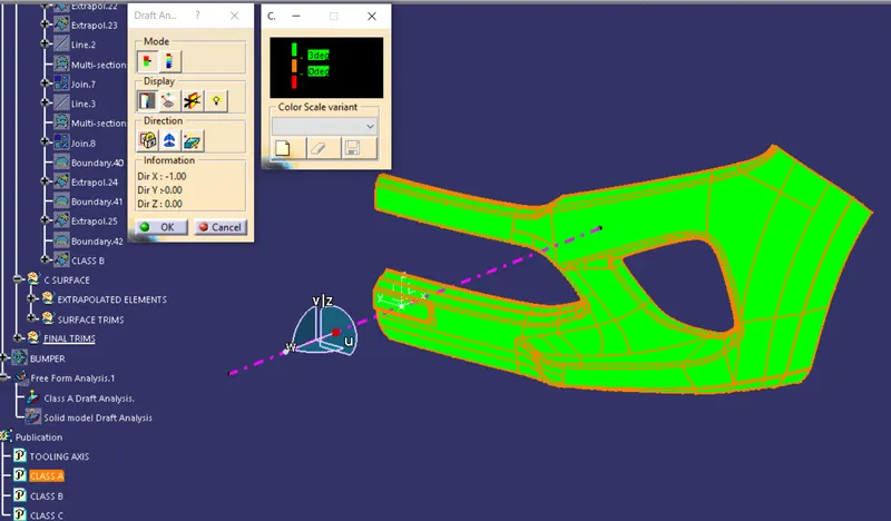
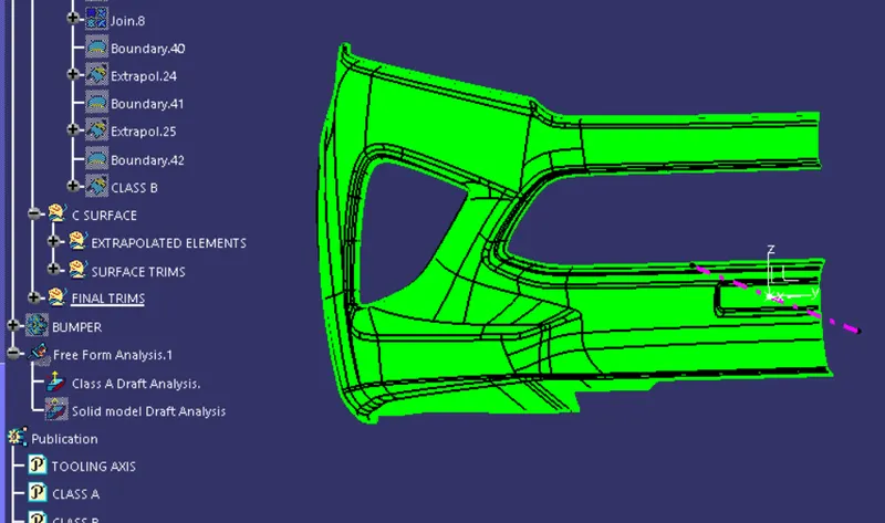
Furthermore, Draft Analysis can be done using the tooling axis that is created, on defining the part body and selecting the draft analysis option selection of direction using the compass and redirecting to the tooling axis will be the reference for the draft analysis. On selecting the surface the surface will depict the output for the draft angels using a colored scale. By default for a draft angle of 3 degrees or more, it will show green, for 0 degrees it will show red and for the negative draft angle, it will show blue. Additionally, one can use the other mode besides the default mode which is much more detailed with various draft angle ranges which can be used for the desired surface for draft analysis.
Class B on the other hand made with reference to Class A surface that contains the engineering aspects of a model features such as ribs, bosses, etc. It is the surface that is below a certain thickness from the class-A surface, which is why it is not visible and is the inside part. Offsetting the class-A surface to a 3mm inward direction as given.
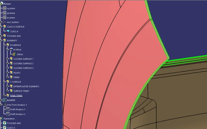
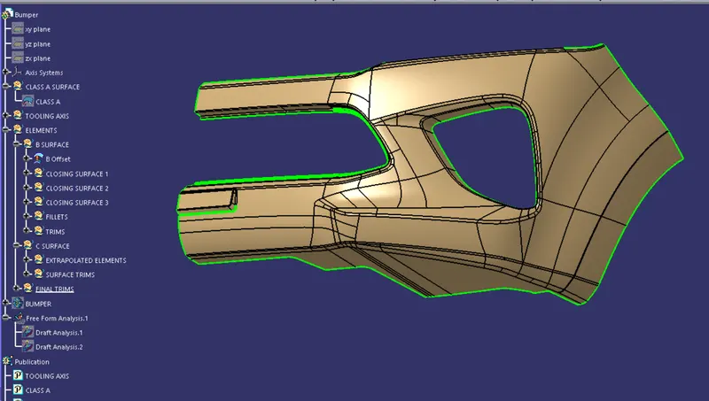
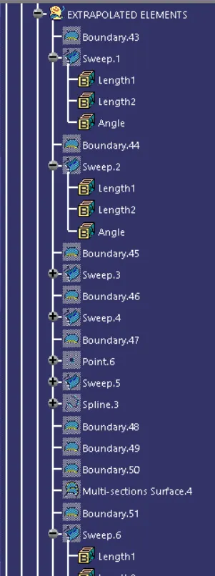
Although, There may or may not be some deformations in some of the patches, especially those areas with some complexity, by redefining those patches and discontinuity of the offset surfaces using the features like extract, multi-extract, sweep, multi-section surfaces, and extrapolate.
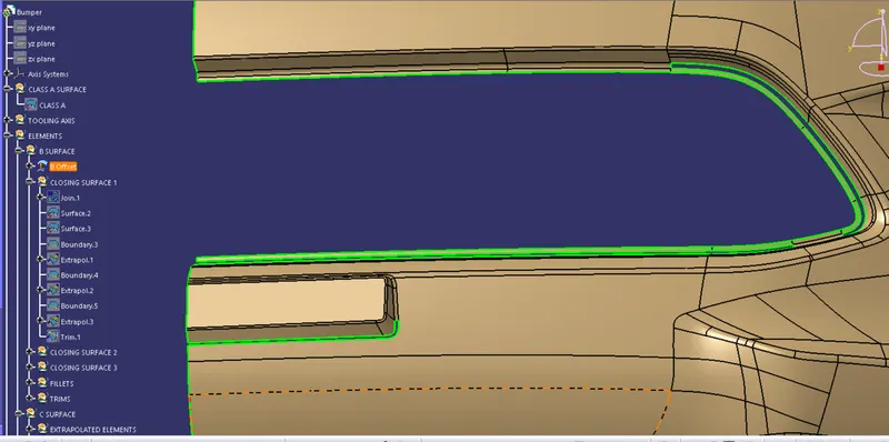
By resolving them,
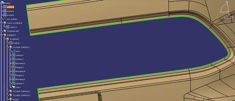
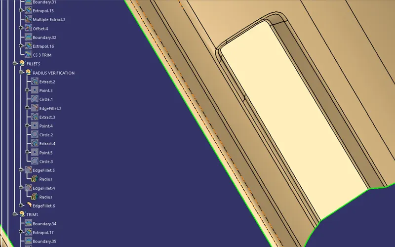
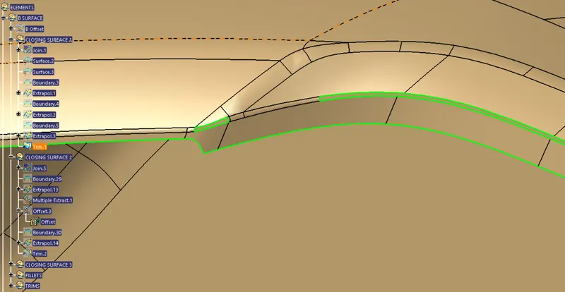
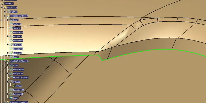
Once the patches are covered fillets can be applied where ever necessary.
To ensure the continuity of the Class-B surfaces checks the boundary command to find out the boundary. Hence class-B surface creation is done.
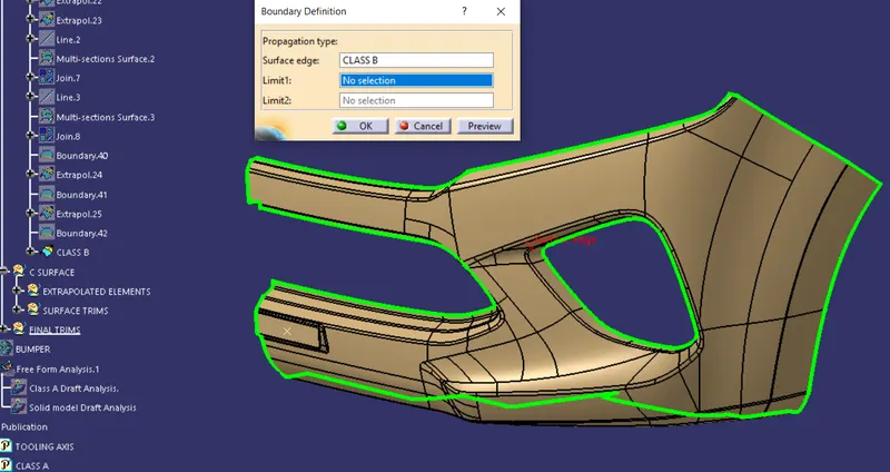
Creation of Class C surface
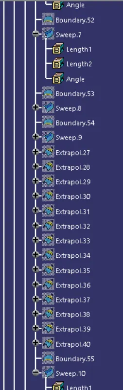
The surface that joins class-A and class-B surfaces are the class-C surface. It is created by using the sweep command with A surface acting as the reference surface with the option With reference to the surface not parallel or perpendicular and a curve created from the boundary of the same surface. Another sweep command used for the surfaces parallel to the tooling axis With draft direction is also used to create A-surfaces.
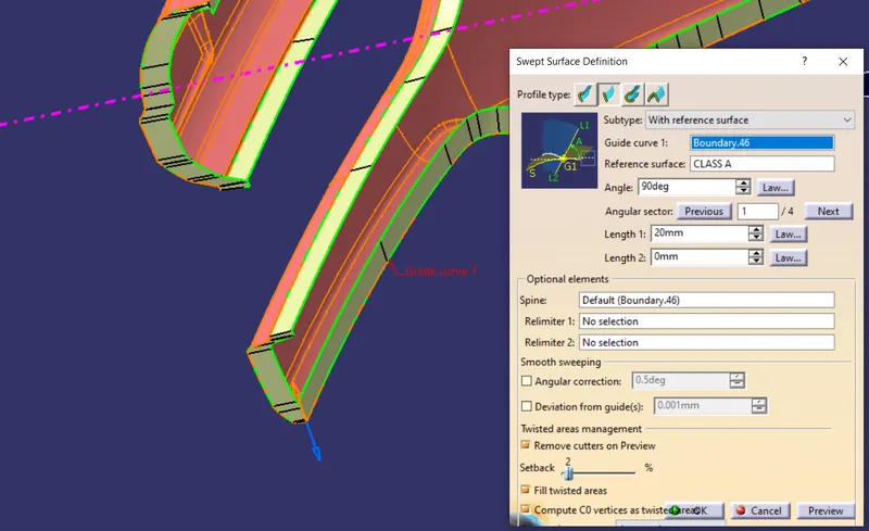
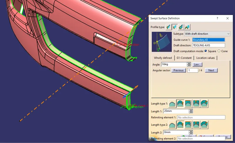
Over the surface formation using the sweep command surfaces are not connected. So, extrapolation and trim are used to connect and to define the Class C surface. Thus CLass C is formed
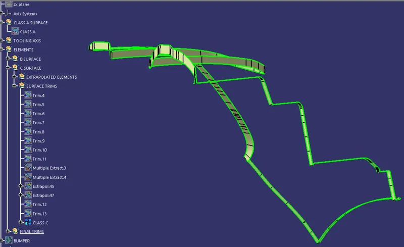
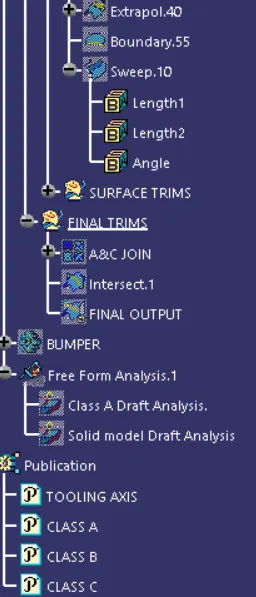
Furthermore, Class A and Class C combined are created by using the Join function
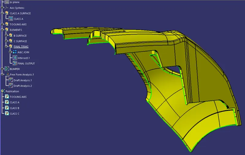
Next, The A&C Join is trimmed off by the inner surface of Class B to obtain Final Output.
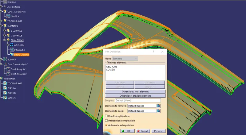
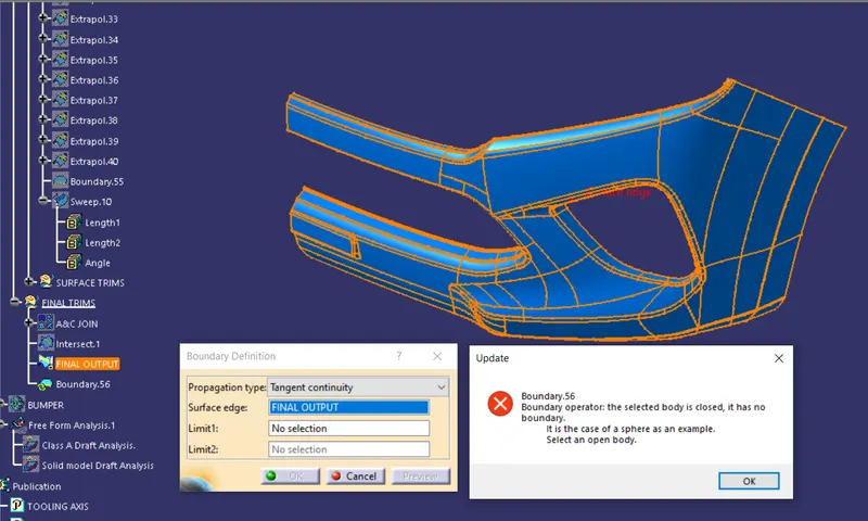
The Final Output Surface model is closed without any boundaries.
Furthermore, the Closed surface Function can be used from the Part Workbench to create the Solid Model for the Bumper.
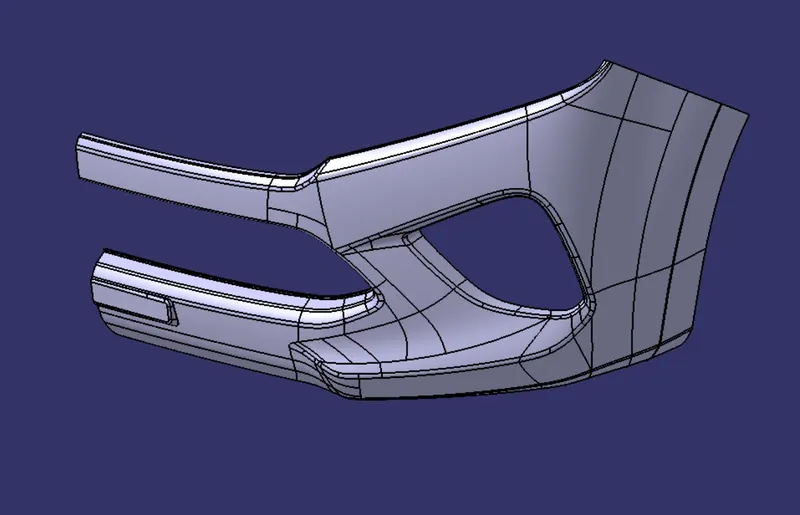
Finally, the Draft analysis is initiated to check the feasibility of the model,
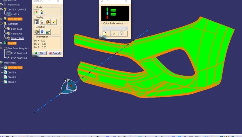
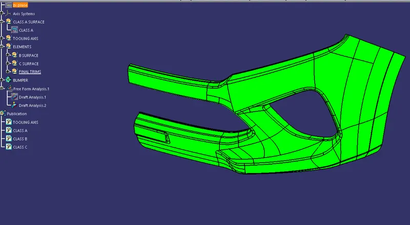
As the analysis depicts the results are positive with the reference to a 3-degree draft angle for the making and inspection for manufacturability of the Bumper with the help of class A surface. The Bumper plastic model is been made.