Week 8 - Challenge 4 - Bumper
Answers:
Report on draft analysis of Given class A surface and soild model of a bumper.
AIM: To do draft analysis on given class A surface and draft analysis on the solid model after creating it from class B and C surface.
Given Class A surface:
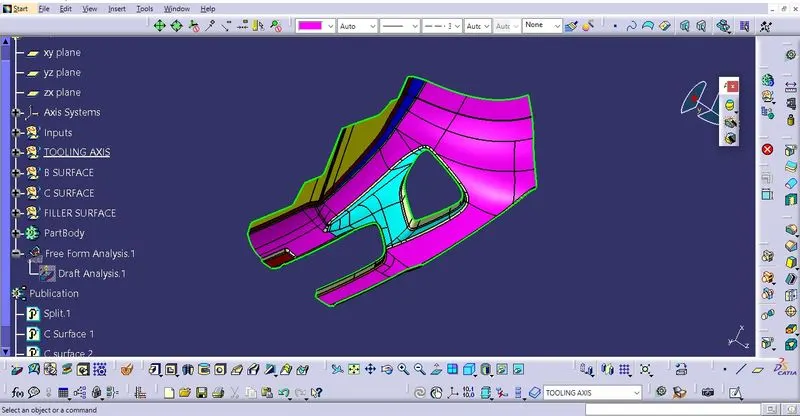
Step 1: Check the connectivity of the A surface ensure that there is no gap between the component.
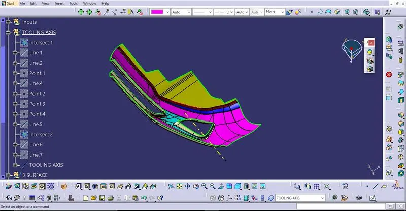
Step 2: Finding the tooling axis of the component. The tooling axis is nothing but the mould opens or cavity opens. Check the best possible tooling axis. First create dummy tooling axis. By creating a line passing through the point at centre of the hole.
Create a tooling axis by bisecting method:
create a point at the centre of hole then create the artificial axis system from that point now intersect the Class A surface with the appropirate plane of the axis system. Now create a bisecting line from two lines adjacent to each other on the intersection curve with taking origin of axis system as reference point. The resulting line is oiur main tooling axis.
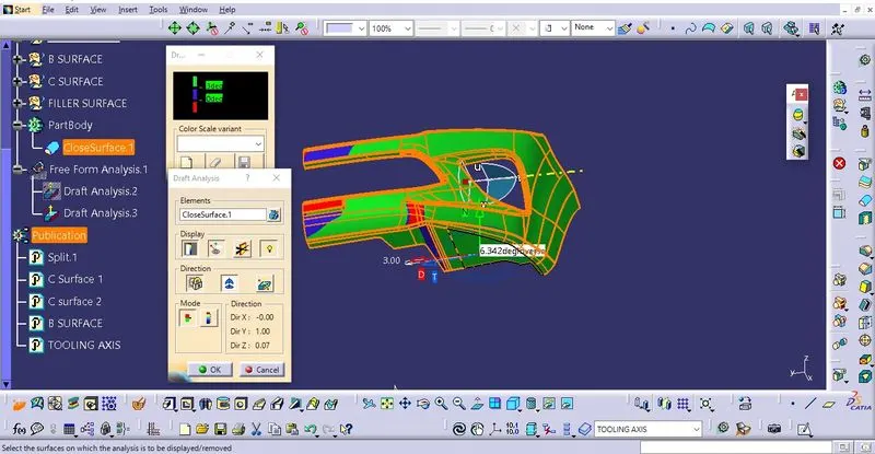
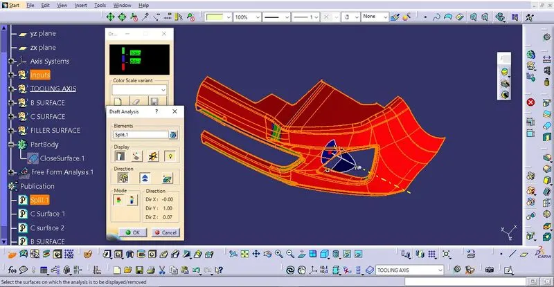
Now perform the draft analysis through the draft analysis toolbar in the bottom. after opening the draft analysis toolbar drag the compass on the tooling axis, click on the lock symbol after compass is aligned.
Step 3: Creating Class B surface
Create Class B surface by using offset command on the Class A surface to create the required thickness on the solid model now modify all those small open boundries one by one by using multiple extract, then extrapolating and trimming the required element of the surface. In this way close all the small boundries to create close B surface.
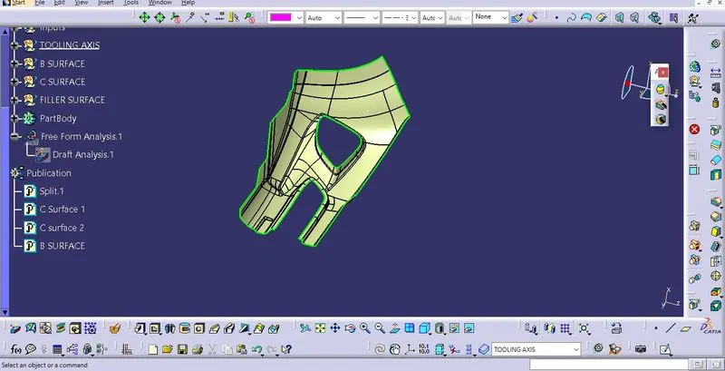
Step 4: Creating Class C surface
Since class C surface is perpendicular to the class A surface, so after extracting the outer boundary walls of class A surface, we use sweep command with angle of 90 degree with reference surface as class A surface and draft operation. With appropirate draft angle.
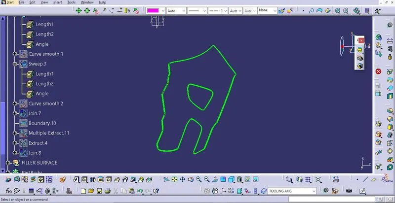
First join the Surface A with Class C surface then finally trim the output with class B surface. And finally use close surface command in the part workbench to create the solid model. Publish the class A, B and C surface by publiction command in the tool menu.
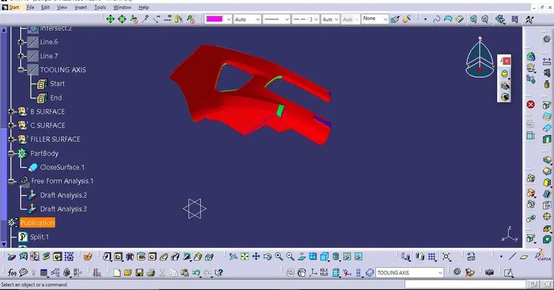
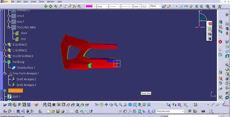
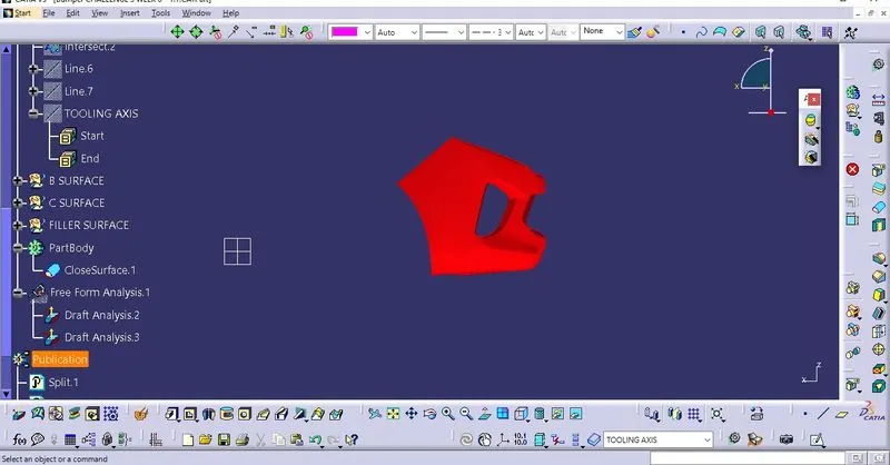
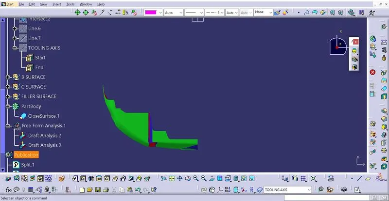
Now do the draft analysis on the created solid model by the help of tooling axis as shown: