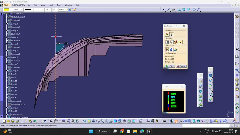
Week 8 - Challenge 4 - Bumper
AIM : Create the Bumper Plastic component through the given Class-A surface taking the thickness of the component be 3 mm
- CREATION OF TOOLING AXIS :
- First ensure that the class-A surface is properly joined and has no discontinuity on it. To check we can use join command or boundary command .
- select the best region or direction suitable for the tooling axis direction by visual or Intersection method .
- After selecting , create a point accordingly using ' POINT ' command .
- Now create a line using ' point to direction 'method along X direction .This is our required Tooling Axis .
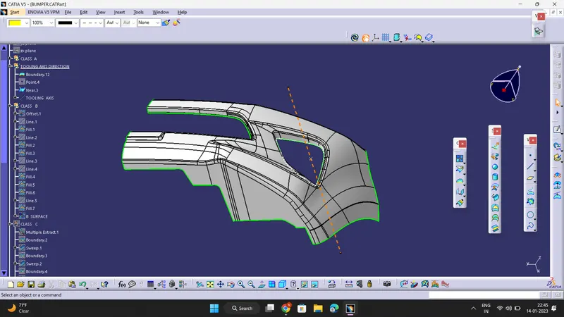
DRAFT ANALYSIS REPORT :
- Follow the steps : Go to insert> analysis> feature draft analysis
- Place the compass on the Tooling axis .
- Select the lock symbol to fix compass along with tooling axis .
- Click on the surface then various Color codes will be appeared and Draft angle is applied . Make sure that the surface is within the permissible limit of the draft values. The surface should be green and nominal draft value should be 3deg .
- Thus the draft analysis on the class-A surface is successfully performed.
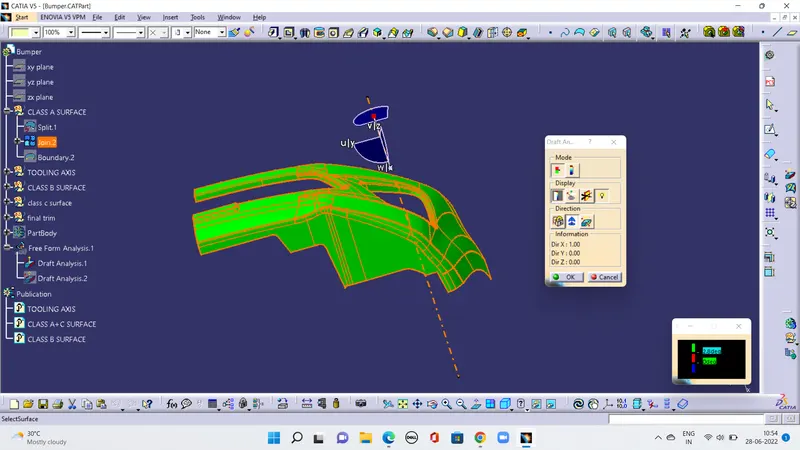
FINAL PLASTIC COMPONENT DRAFT ANALYSIS :
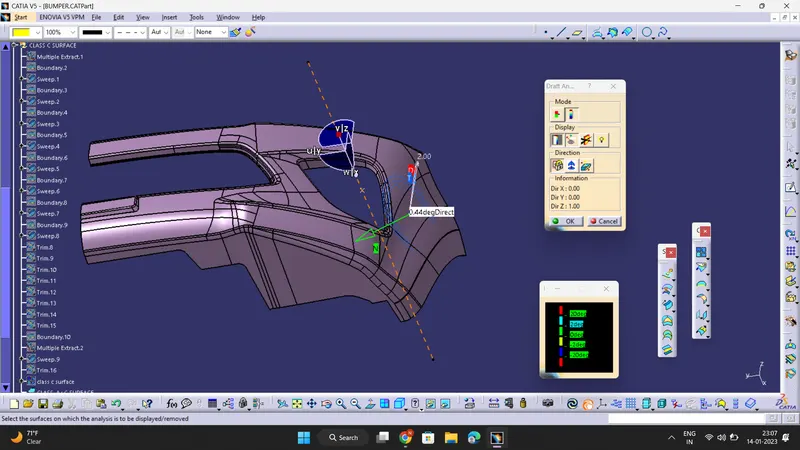
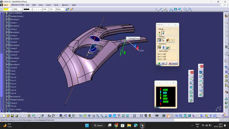
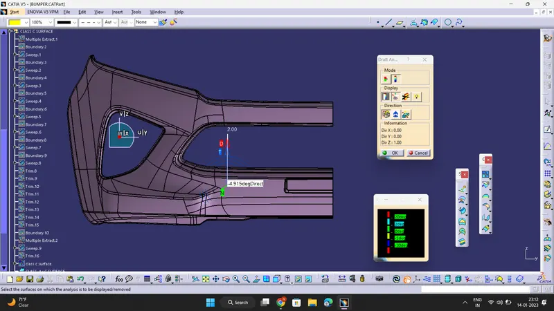
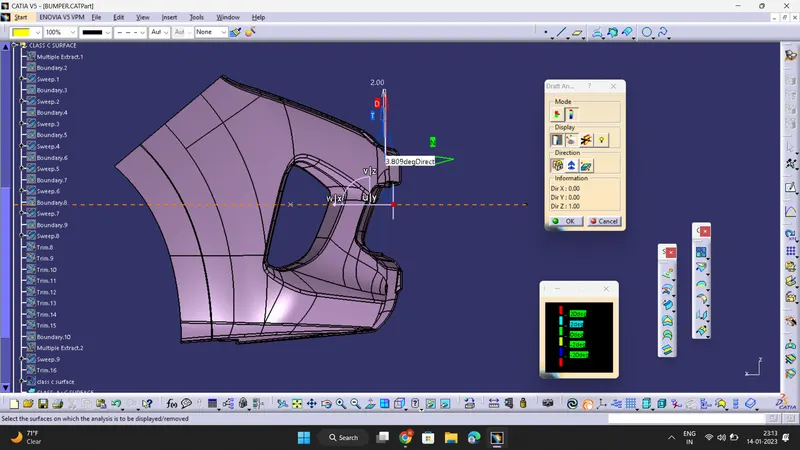
- Screenshots of the solid model with the proper color code of the draft angle in various orientations (Isometric, Front, Side, and Top View) :
ISOMETRIC VIEW :
FRONT VIEW :
SIDE VIEW :
TOP VIEW :