Week 8 - Challenge 4 - Bumper
BUMPER DESIGN
OBJECTIVE
The current objective is to Create the Bumper Plastic component through the given Class-A surface.
STEPS
Below are the steps to systematically create the plastic component:
- Tooling Axis Creation
- Draft analysis
- B Surface Creation
- C Surface Creation
- Final Trim and make sure it becomes a closed surface.
- Solid Body Creation from the closed surface.
TOOLING AXIS CREATION
The starting will be from the creation of tooling axis. we need to select the tooling axis so as it is the optimum orientation for the component production in real life. Generally, first we look if its okay for the tooling axis to be in the XYZ directions. If thats not possible, then we will look for large, flat surface and take the tooling axis normal to the surface. If that is also not possible, then we will create tooling axis with bisecting method.
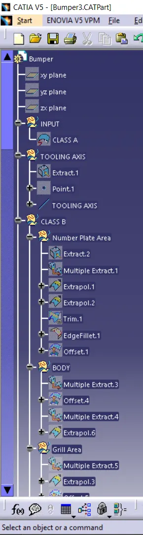
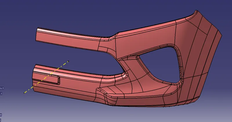
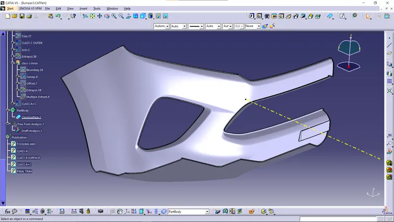
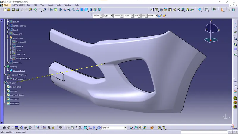
Here what we done is, extracted a flat surface from the number plate area, made a point in the suface and created a line from that point in the x direction.
DRAFT ANALYSIS
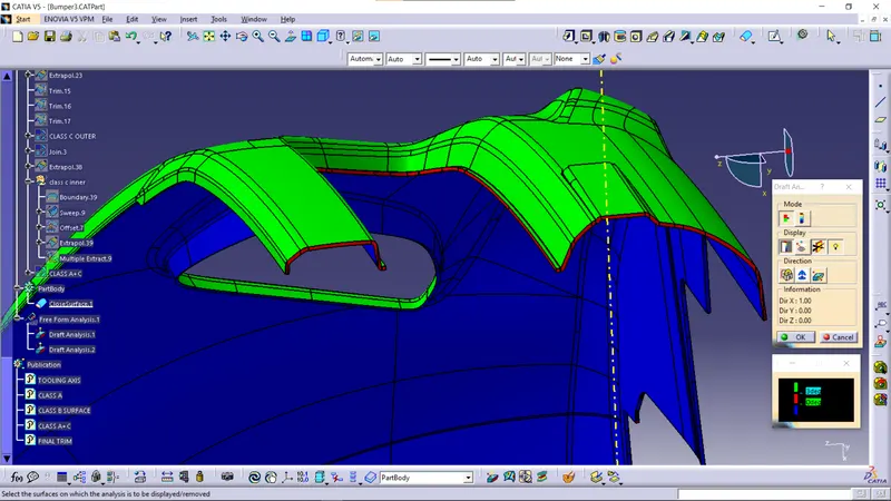
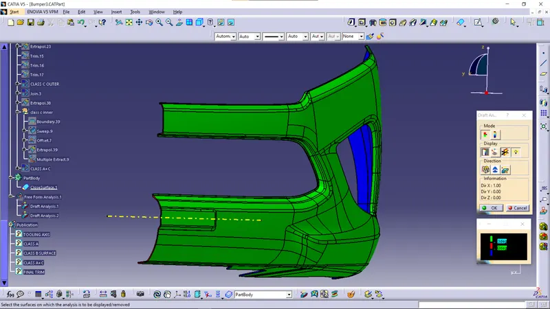
Click on the Feature Draft analysis icon.
Use the compass to Select the tooling axis as the direction.
Adjust the color scale to 3 degree.
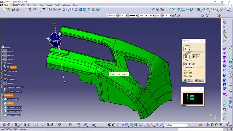
As we can see from the above figure, draft is not possible for the side and lower portion of the bumper. At those areas, we can make the class c surface perpendicular to the reference surface.
B Surface Creation
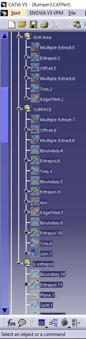
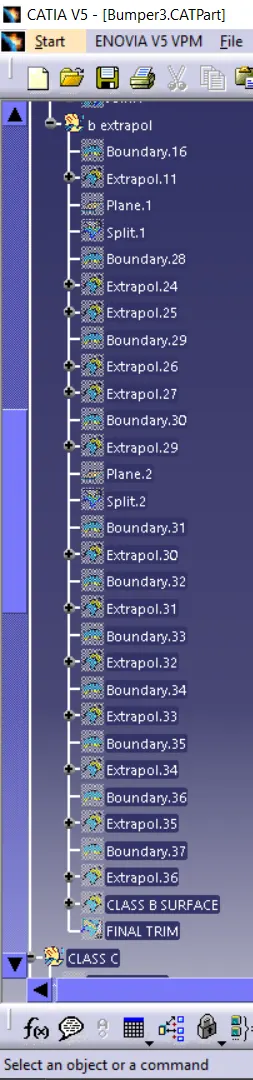
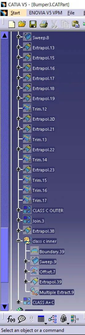
The specified thickness for the component is 3mm. Offset the class A surface 3mm in the inside direction. Some of the sub elements will not be offsetted very well. Such areas needed to be extracted individually and offsetted. For completing the surface b, operations such as extract, multiple extract, offset, split, trim, join, untrim, extrapolate, boundary, sweep, fillet etc are used.
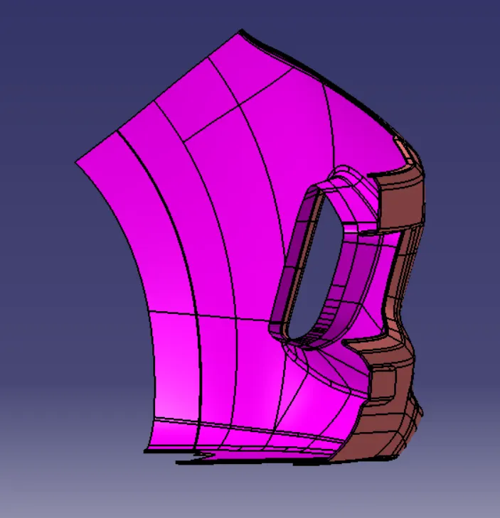
Class C surface creation
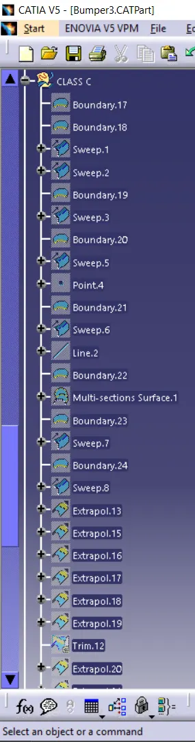
In the front areas like the grill portion, c surface is made with draft direction with respect to the tooling axis using sweep operation. The other areas where draft is not possible with respect to the tooling axis, c surface is made perpendicular to the reference surface, which is the class A surface.
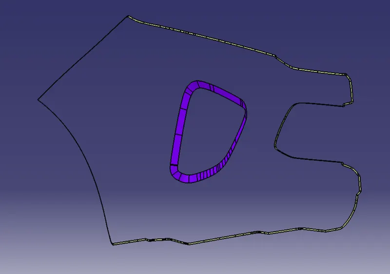
Trimming
The class A surface and class C surface is trimmed and then then it is trimmed with the class B surface to create a closed surface.
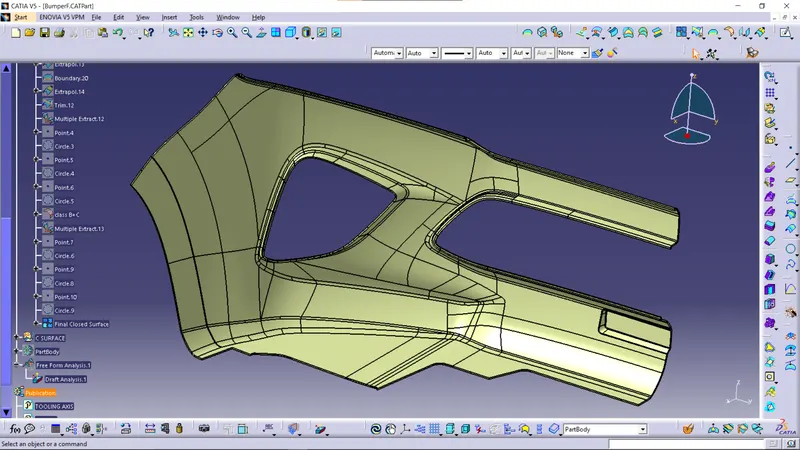
Solid Body Creation
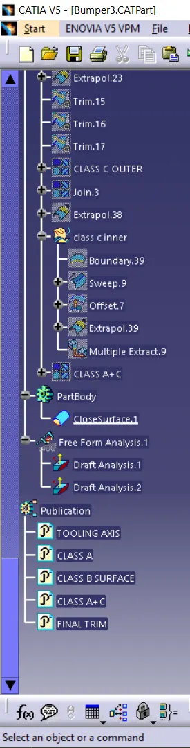
Switch to Mechanical Part Design Workbench and select the closed surface operation in the surface based features. Define the part body and select the closed surface. The solid body wiil be created.
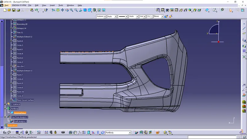
DRAFT ANALYSIS
TREE