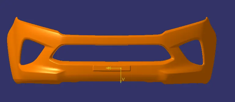
Week 8 - Challenge 4 - Bumper
CLASS-A SURFACE:
The class-A surface is used in the automotive design industry. it describes the final production surface data for the aesthetic parts.
CLASS-B SURFACE:
The class-B surface is the second surface that has a specific thickness from the class-A surface. this surface contains engineering aspects of a model. These must be smooth and "error-free" as well but are not held to the standards that class A surfaces are.
CLASS-C SURFACE:
The Class C finish allows more imperfections than Class A or B. Class C is often specified for interior surfaces not readily visible, surfaces that will be covered by another part when assembled, or surfaces.
Design methodology:
- Insert the class A surface of the Bumper in CATIA software.
- Determining the tooling axis for the Bumper
- Creation of class B surface.
- Creation of class c surface.
- Join the bumper class A, class B, and class c surfaces and ensure all the surfaces are closed surfaces.
- Use the Close Surface feature to make a solid body from the surface.
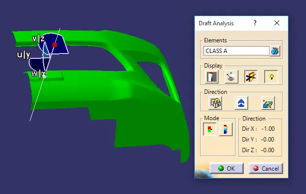
- Finally, Perform the Draft analysis on the bumper plastic component.
Creation of Tolling axis:
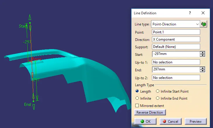
To create the tooling axis first we have to check the best suitable direction for tooling by using the compass. the x direction is suitable for creating the tolling axis because in the x direction most of the surfaces are clearing while performing draft analysis. Choosing the parallel surface to create a tooling axis. Create a line perpendicular to the surface.
CREATION OF CLASS B SURFACE:
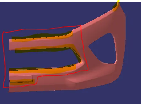
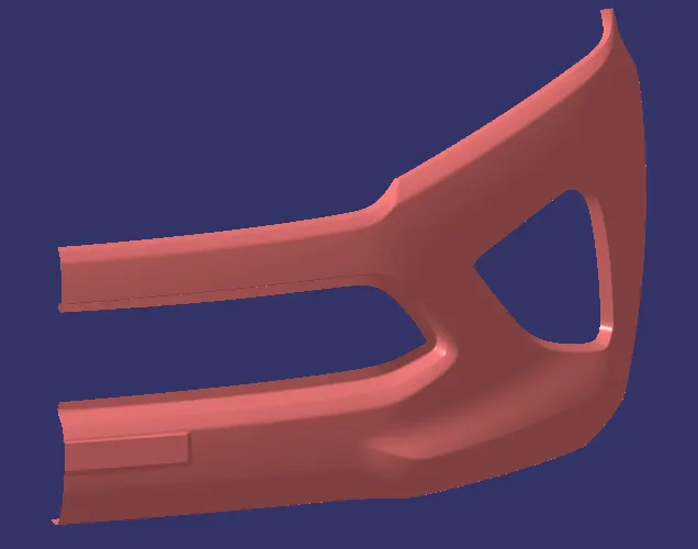
In this component Creation of the class B surface first, we have to offset the entire model by 3mm inward some of the surfaces give offset error and ask for offset without these subelements click okay and work on the incomplete surfaces by using the multi-section surface command, sweep and different commands used to complete the class B surface.
OFFSET SURFACE 3mm
CLASS B SURFACE
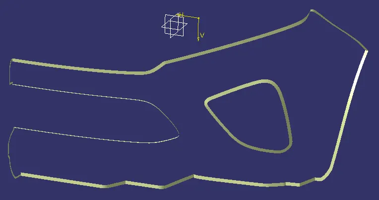
CREATION OF CLASS C SURFACE:
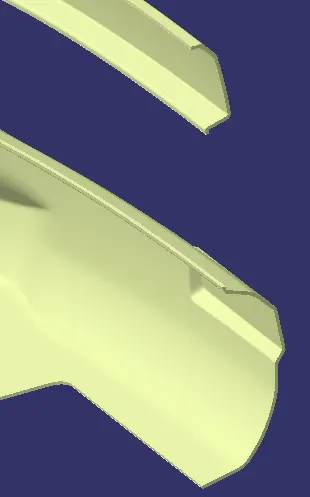
We first extract the edges from the Class A surface with the help of the multi extract or boundary command which we create the path for a sweep for class C.
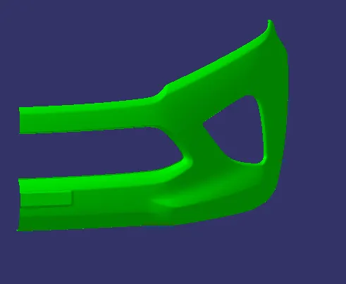
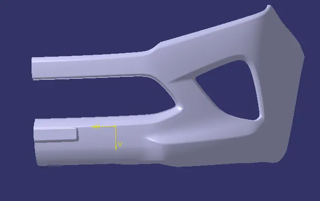
Final Plastic Component.
Then trim the class-B surface to join (A+C) this will make sure that we get a closed surface. We can check it using the boundary tool, if it gives an error that means that the component is closed.
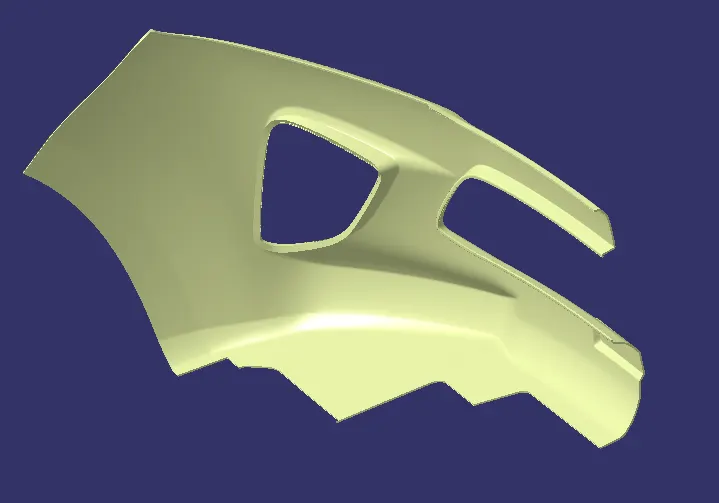
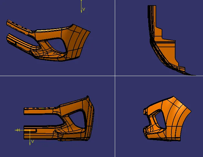
Final Solid Body:
Using close surface in part workbench the final plastic Body is Created.
Draft analysis of the final plastic component:
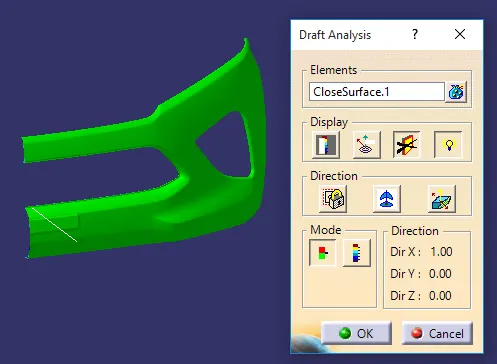
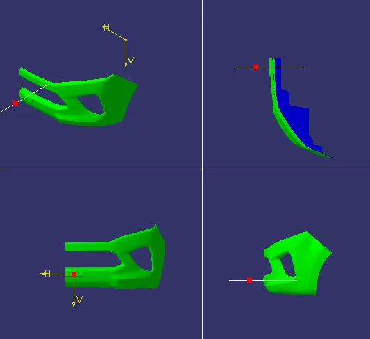
The Bumper Plastic Component is created from Class A and Draft analysis Is performed.