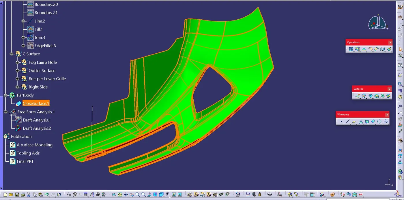
Week 8 - Challenge 4 - Bumper
Draft analysis,
The Draft Analysis command enables you to detect if the part you drafted will be easily removed. This type of analysis is performed based on colour ranges identifying zones on the analyzed element where the deviation from the draft direction at any point, corresponds to specified values.
Tooling axis,
- In Molding machine the opening is done in mould along a direction which is known as Tooling Direction.
- The mould is built from two separate halves (Core and Cavity) and tooling direction basically defines the direction of mould pulls apart.
- Tooling direction is known as primary direction.
- This provides the job ejection pin and were the injectors are placed.
Creating the tooling axis, particularly the Bisecting method
- The A-surface was imported into CATIA and checked for irregularities by using Join, Boundary and Disassemble option.
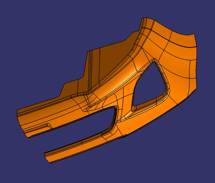
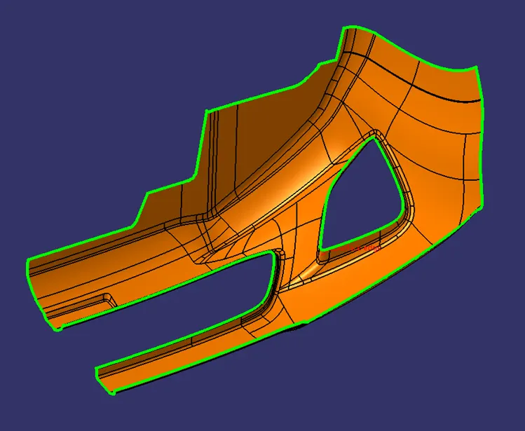
- Using Extract option, Extract the base surface and create the point.
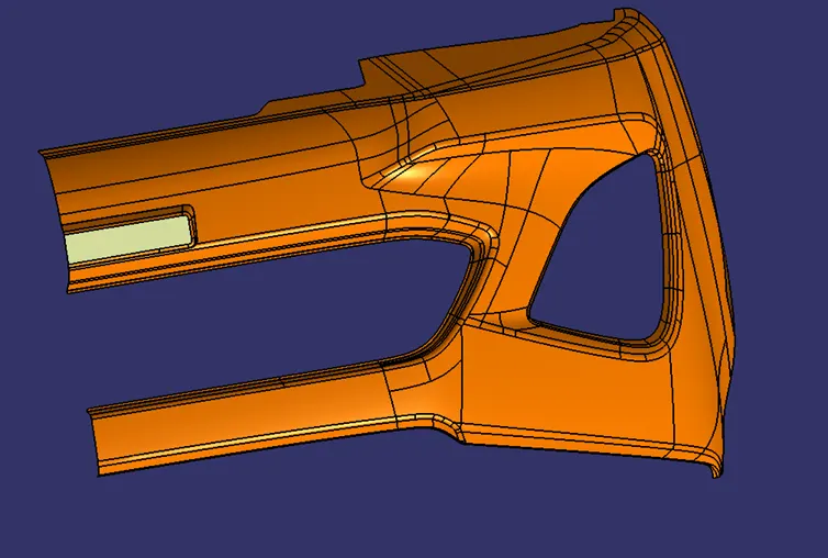
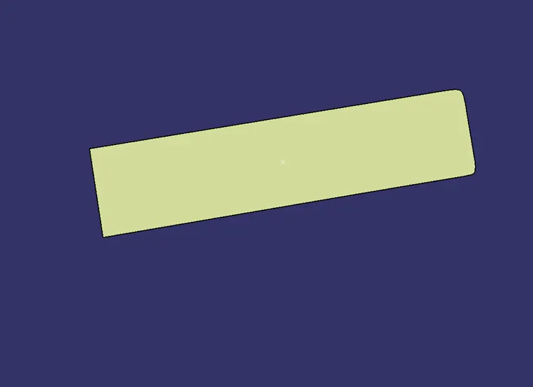
- Insert the Axis system with respect to the point which was created.
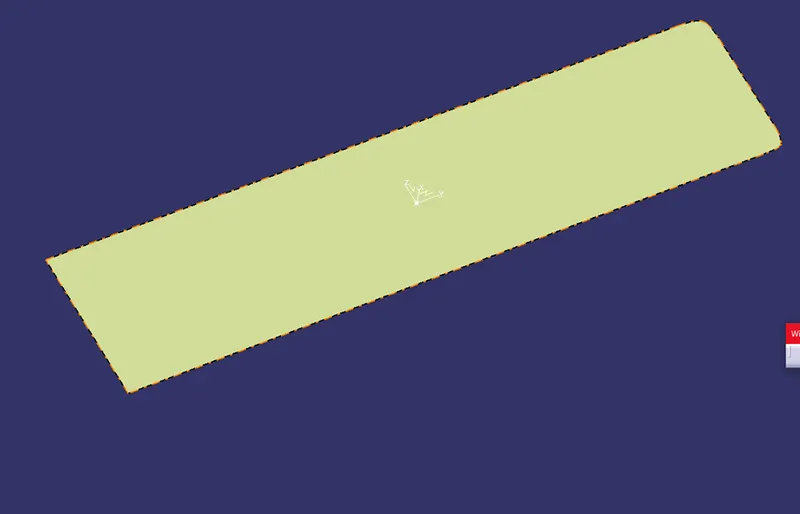
- Finally by using the point the tooling axis were created by selecting the tooling axis x direction and y direction axis.
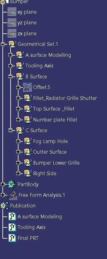
Tree Structure
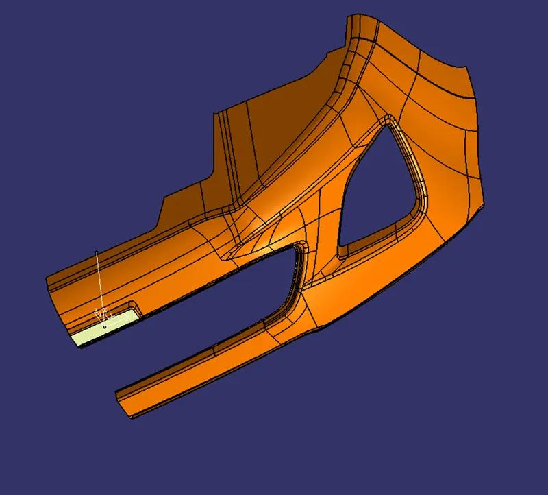
Isometric View
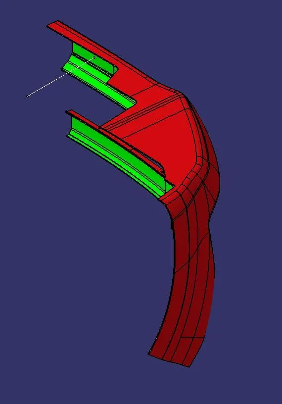
Front View
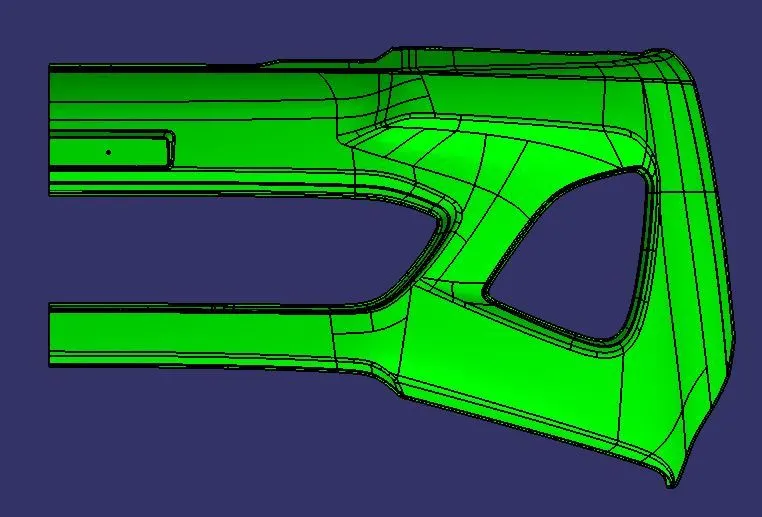
Side View
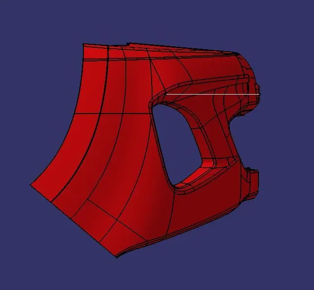
Top View
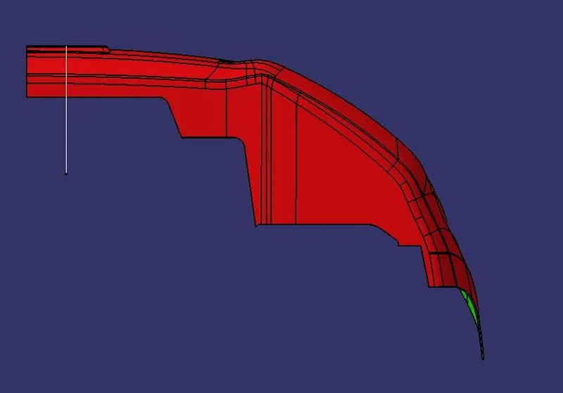
Class-A surface Draft
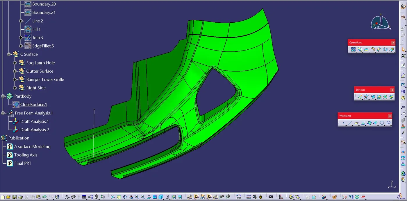
Final plastic Draft