Wiring harness routing & packaging Rules Week 3 Challenge
Wiring harness routing & packaging Rules Week 3 Challenge
Introduction:
- Defining the P-clamp as Electrical support using Electrical Part design Workbench and their necessary properties.
- Defining Tyco 1738312-1 Back shell cad data as Electrical back shell using Electrical Part design and their necessary properties.
- Creating the Following Corrugated tubes & adding them in Catalogue under “Slit COT” family.
|
Name |
ID (mm) |
OD (mm) |
Thickness (mm) |
|
15mm COT |
12 |
15 |
1.5 |
|
20mm COT |
17 |
20 |
1.5 |
|
35mm COT |
32 |
35 |
1.5 |
|
10mm COT |
7 |
10 |
1.5 |
|
5mm COT |
3 |
5 |
1 |
Procedure:
- Defining the P-clamp as Electrical support using Electrical Part design Workbench and their necessary properties
- Download and insert the .iges file to Catia V5 part design.
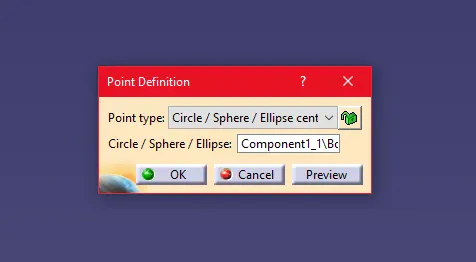
- Create Entry point and exit point parallel to each other. To create centre point, select the point command and select circle/sphere/Ellipse and select the diameter. Create another point parallel to point.
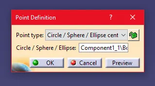
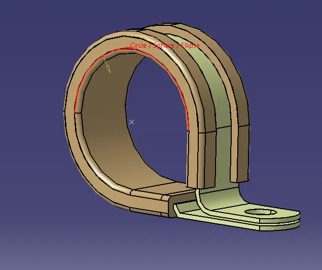
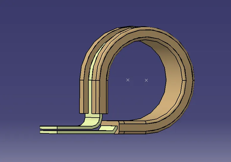
- Create Entry plane, Exit plane and Base plane with corresponding to the point which was created.
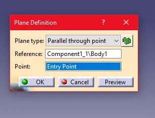
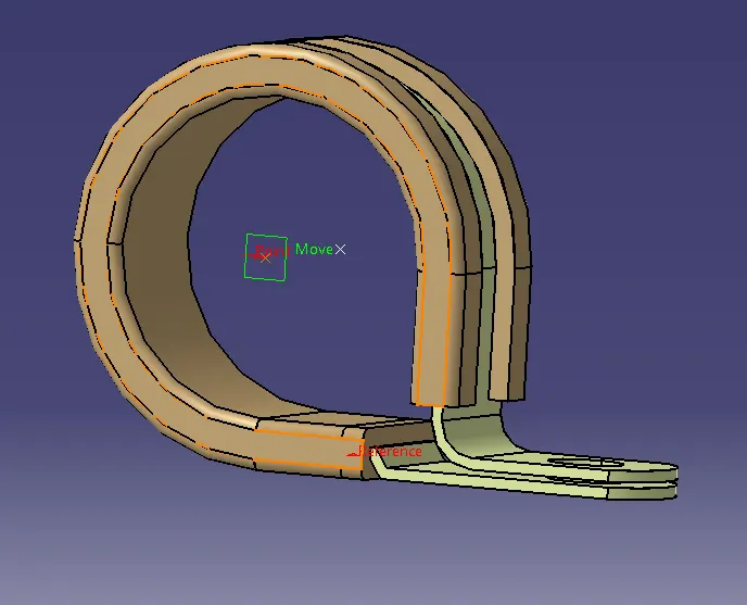
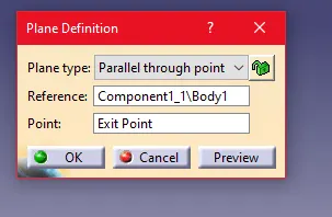
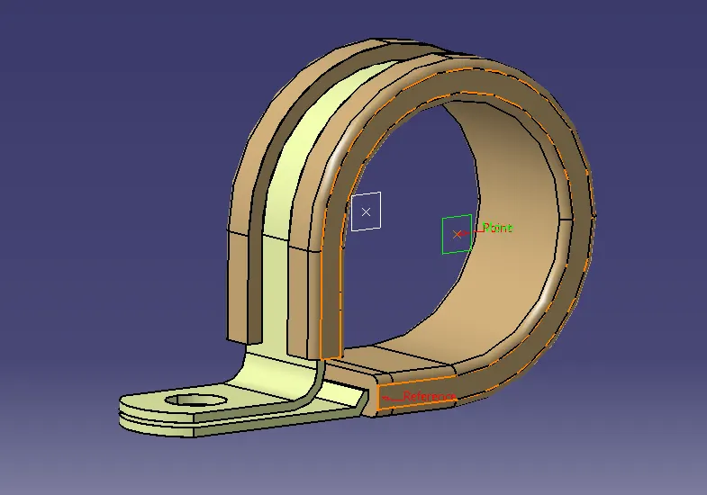
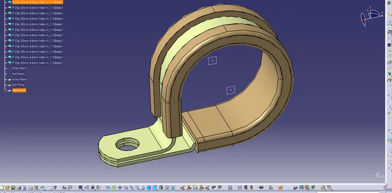
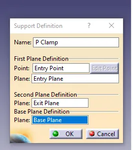
- Once the Planes and points are created switch the workbench to Electrical workbench, were we can find the define support command to define the P Clamp into electrical part. Select the part and Provide the Entry parameter

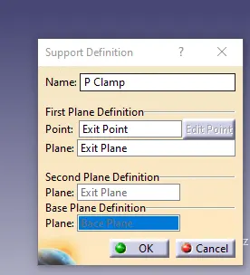
Once the Entry parameter added, again select the define as support command and Provide the Exit parameter
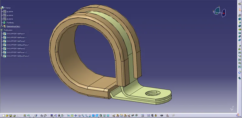
- Hence the P-clamp is defined as electrical part and defined with necessary parameter.
- Defining Tyco 1738312-1 Back shell cad data as Electrical back shell using Electrical Part design
- Download and insert the .iges file to Catia V5 part design.
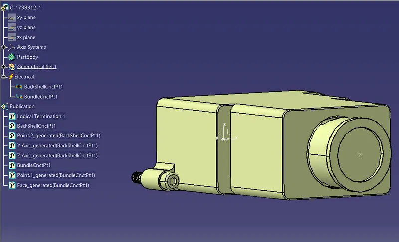
- Create Point on Bundle entry and opposite to the bundle entry using point command.
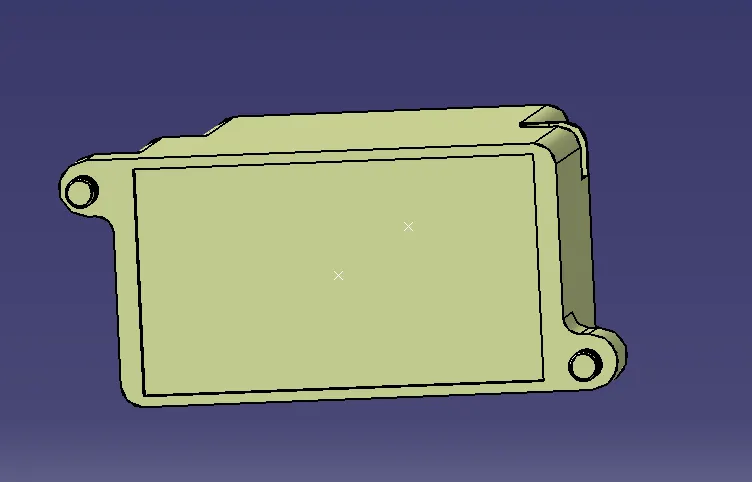
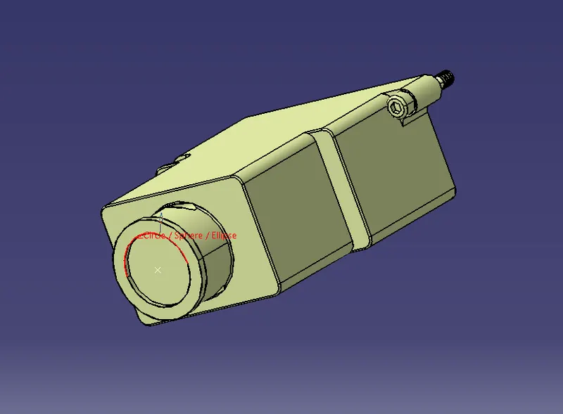
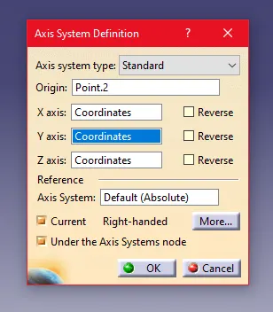
- Create Axis on Back shell point. The X and Z axis can be in any direction meanwhile the y-axis must be perpendicular to the Point.
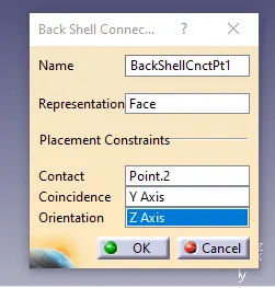
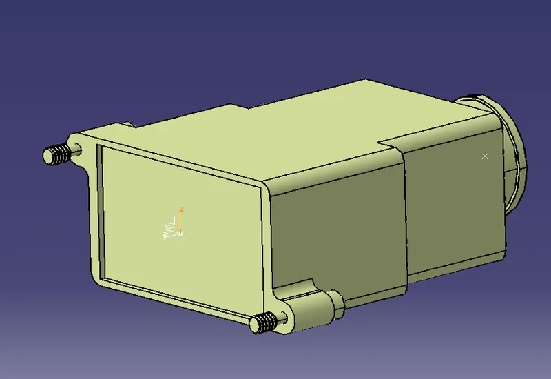
- Once the point and axis is created, Change the workbench to electrical workbench.
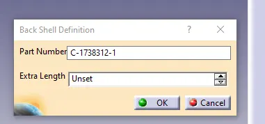
- Define the back shell using the define black shell command. Use Extra length as unset. Provide the representation as face, Contact as point, Coincidence as Y axis and Orientation as X-axis or Z-axis.
- Define the Bundle entry point to the Back shell.

- Hence the Tyco 1738312-1 Back shell cad data has been electrically defined.
- Creating the Corrugated tubes & adding them in Catalogue under “Slit COT” family.
- Open Catia and select Electrical part design workbench.
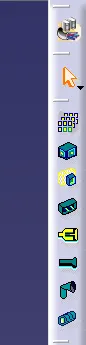
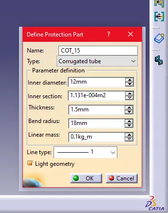
- Select the part Tree and click on the Define Protection part. Since we are creating the 15mm corrugated tube. Provide the following details in the dialog box.
|
Name |
User given |
|
Type |
Corrugated Tube |
|
Inner diameter |
12 mm |
|
Inner Section |
Automatically generated |
|
Thickness |
1.5mm |
|
Bend Radius |
1.5 times of the diameter. |
|
Linear Mass |
.01kg_m |
Insure that the light geometry is always selected.
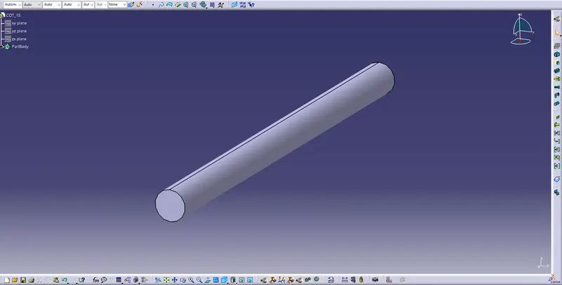
- Save the File in order to save to Catalogue.
- To create catalogue go to “File --> New--> Catalogue Document.”
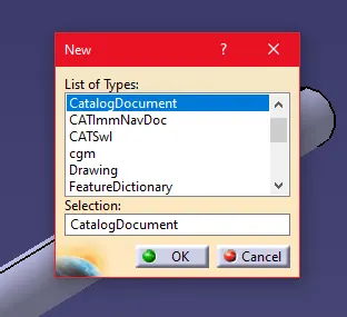
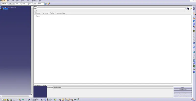
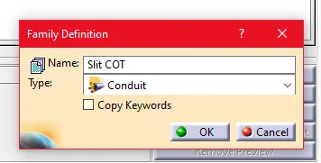
- Once the catalogue document is open select the Add family from the tool tree. Provide the name as SLIT COT. And type as Conduit.

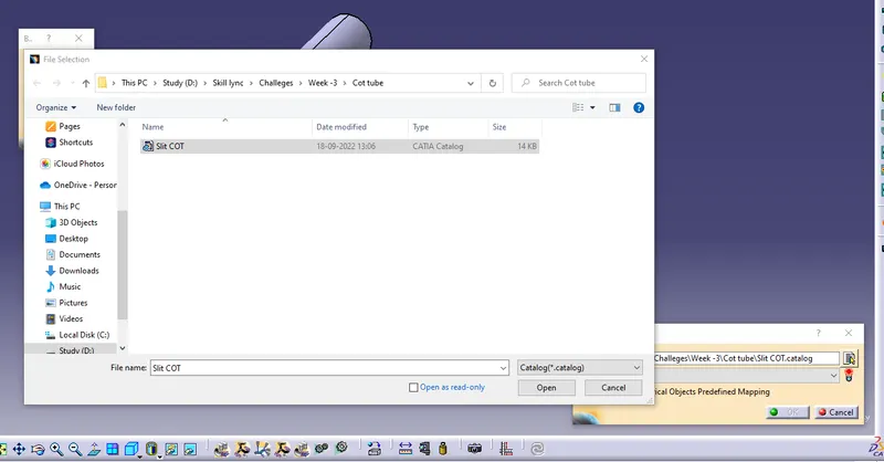
- Save the catalogue to the local drive.
- Once the Catalogue is Created and Saved. Store the Created Corrugated Tube to SLIT COT catalogue using the Store device command. Select family as Slit COT.

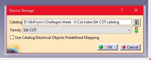
- Follow the same process to create the 20mm, 35mm, 10mm, 5mm Corrugated tube.
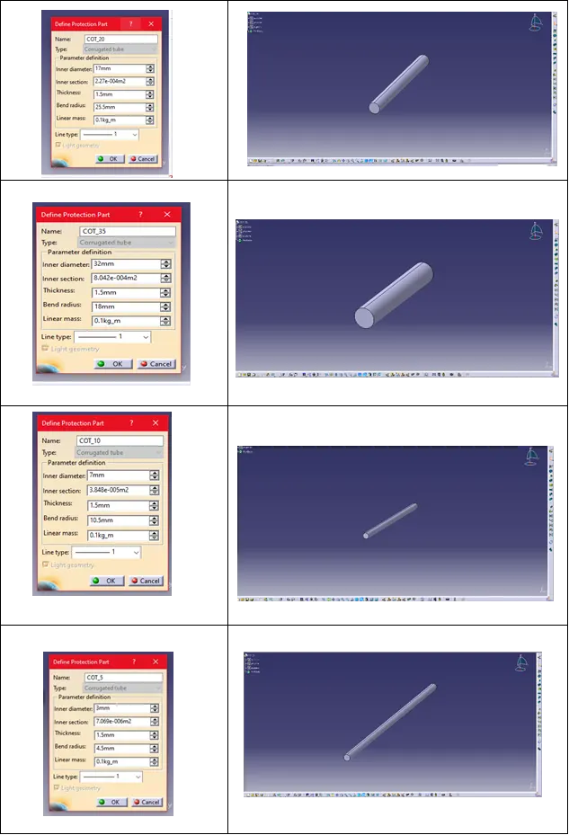
Hence the Corrugated tubes are created and added them in Catalogue under “Slit COT” family.