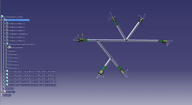
Wiring harness design in CATIA V5 - 3D modeling Week 4 Challenge
Wiring harness routing & packaging Rules Week 4 Challenge
Introduction:
- To Route the following harness layout in Electrical workbench and use the following connectors and define the properties.
- DT06-4S
- DT06-6S
- DT06-2S
- DT06-088SA
- Add protective covering on all branches connected to DT06-2S & DT06-4S connectors. Keep end extremity at 30mm (from connectors end)
Procedure:
- Insert the .iges or .stp file of Connector to Catia V5 software.
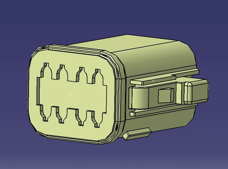
- Once the file is inserted, Using part design create a point for Bundle entry point and Connector connection point.
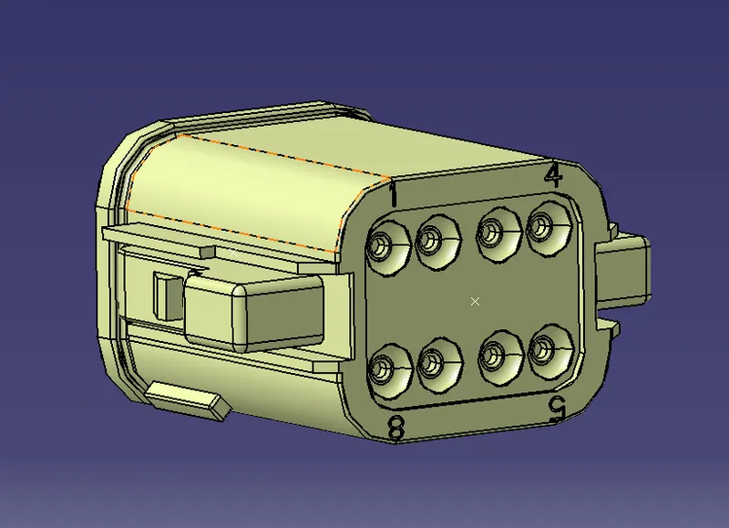
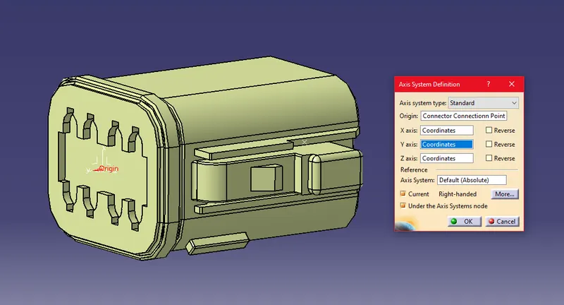
3. After creating the point, define the axis to Connector connection point.
Axis creation:
- X-axis – Pointing towards the Lock
- Y-axis- Pointing towards the front (Connector End)
- Z-axis across the connector (Left to right)
- Change part design to electrical part design to define electrical properties to the Connector.
- For defining the connector, use the icon “Define Connector” and give number of termination as 8.
For defining the bundle Connection point, use the Icon “Define Bundle Connection Point” and give the following details in the dialog box.
Representation- Face
Point- Bundle entry point
Initial condition- Face
- For Defining Connectors Connection point, use Icon “Connectors Connection point” and add the following details.
- Representation- Point
- Contact- Face
- Coincidence- Y axis
- Orientation- X axis.
Once the following parameters are given the part is changed to electrical part with properties and publications.
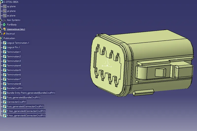
Follow the step for all the connectors and save the file.
6. Design the layout in part file.
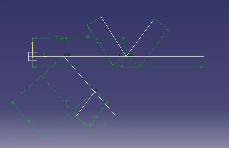
7. Save the part as layout.
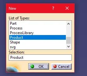
8. Open Fileà Newà
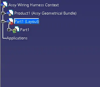
9. Rename the Tree structure as Assy Wiring Harness context. And sub tree as Assy Geometrical Bundle.
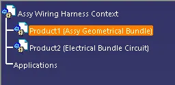
10.Add the connectors using catalogue or from saved file.
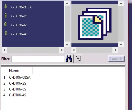
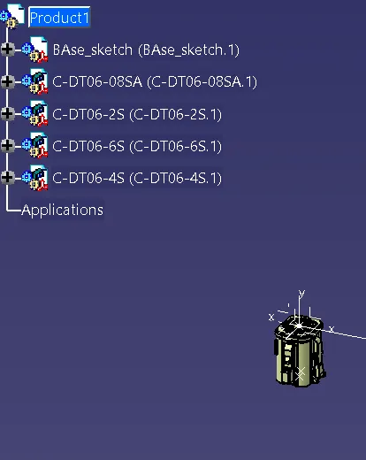
11. Add the layout of the sketch in Sub tree.
12.Using the Assembly design move and place the connectors using move commands in the respective position.
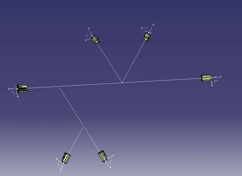
13. By using Geometrical bundle command define the connectors so that the bundle can be created.

14. Using multi branchable command create the bundle by selecting the connectors end to end.
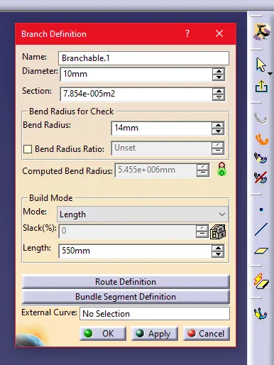
Use the bend radius ratio as 1.4 and build mode as slack with 0 % Slack. Select the route definition and create the bundle.

15. Using Protective Covering command create the corrugated tube on the Wire bundle.