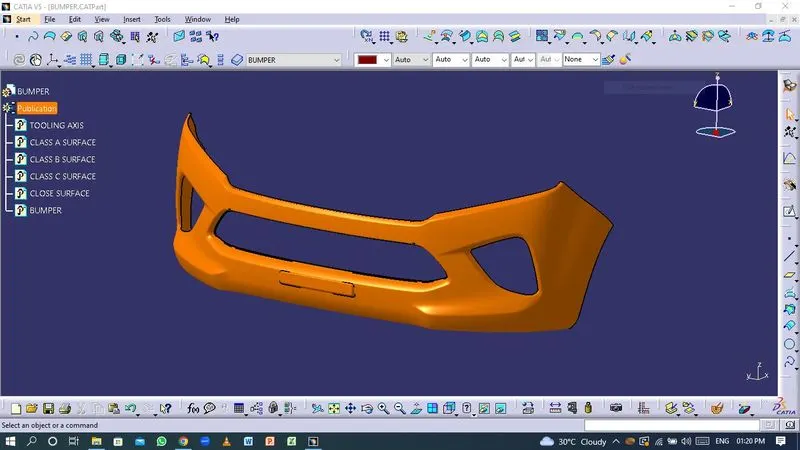
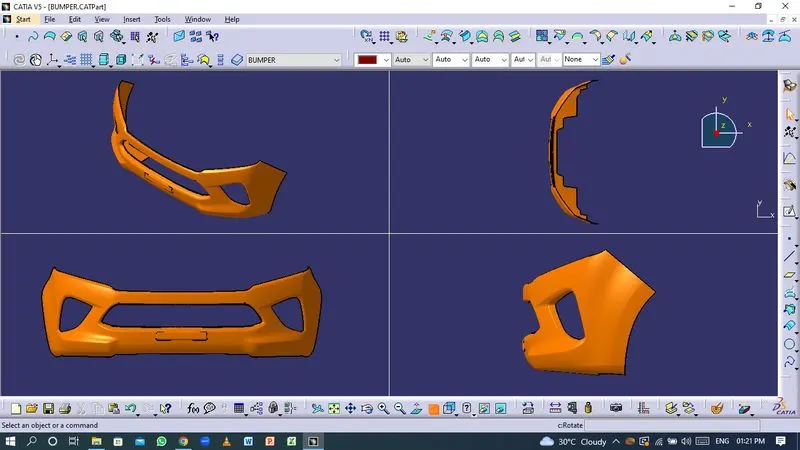
Week 8 - Challenge 4 - Bumper
Aim
- To create the Bumper Plastic component through the given Class-A surface with the required Draft angle and perform Draft analysis on the model.
Software used
- CATIA V5
Given Class-A surface
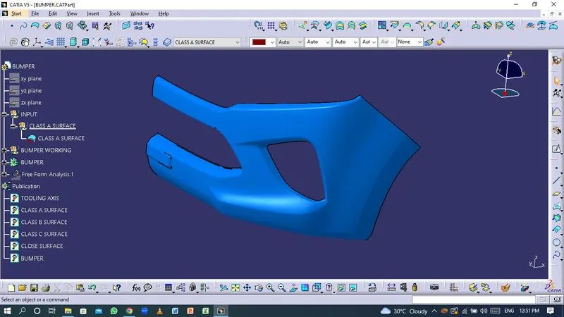
- The Class-A surface is the outermost surface of the plastic component which is also looks fine surface and it is the aesthetic surface that the designer creates as an input part for the design work.
Tooling Axis
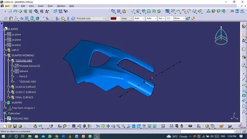
- In Molding, machine arrangement is given to open the mold along a direction which is known as Tooling Direction. In other words. The mold is built from two separate halves (Core and Cavity) and tooling direction basically defines the direction of mold or core pulls apart.
- The tooling axis is created by Bisecting method.
- Bisecting method : This technique is used to generate tooling axis for that purpous. First, the direction of molding must be decided. Next, a dummy tooling axis is created for the purpous of reference. With this approach, we pick the surfaces that could cause issues and consider intersections in the x and y directions. Using these curves, we create two lines, from which we create a bisecting line in both x and y directions. Tooling axis clearing x direction and tooling axis clearing y direction are the terms used to describe how the clearing is carried out.
Creation of Class-B surface
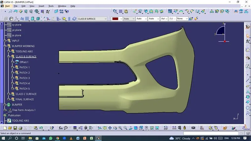
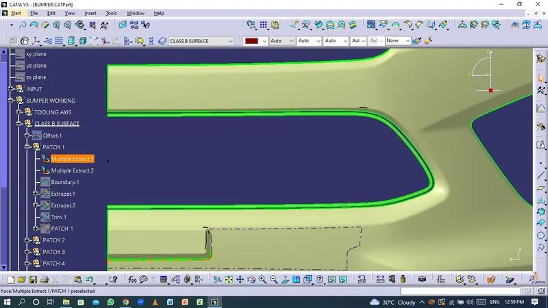
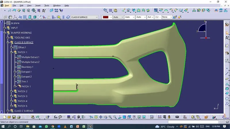
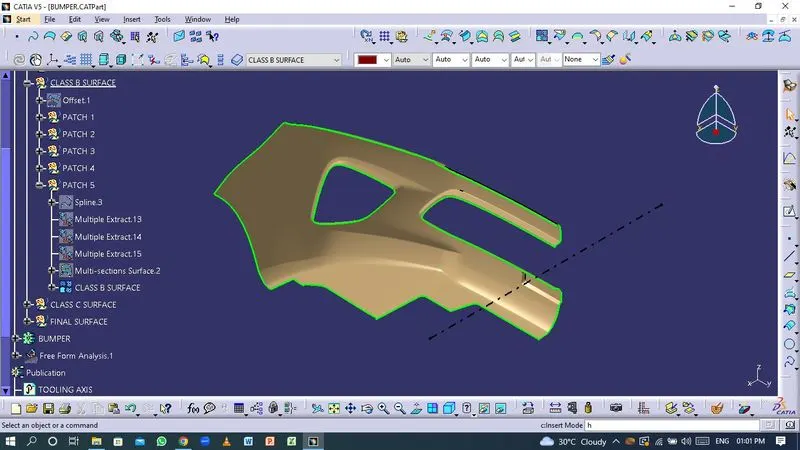
- The Class-B finish is a quality finish with only minimal imperfections. A Class-B finish is the most common finish for exterior surfaces. It is normally specified on surfaces such as external covers, panels, and parts that are fairly prominent.
Creation of Class-C surface
- The Class-C finish allows more imperfections than Class-A or Class-B. Class-C is often specified for interior surfaces not readily visible, surfaces that will be covered by another part when assembled, or surfaces which the Customer feels do not need to meet a high cosmetic finish.
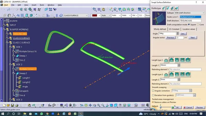
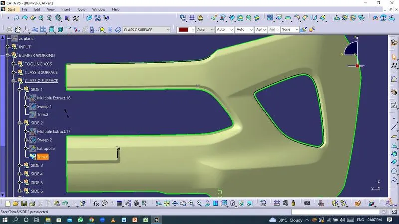
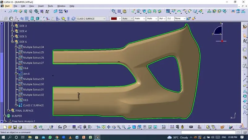
Final surface
- The Class-A, Class-B and Class-C surfaces are joined together to form a closed surface.
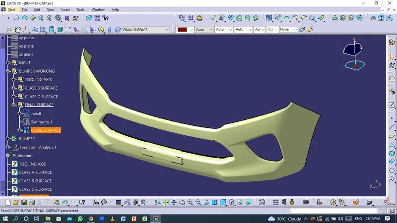
Final Plastic Component
Thickness : 3 mm
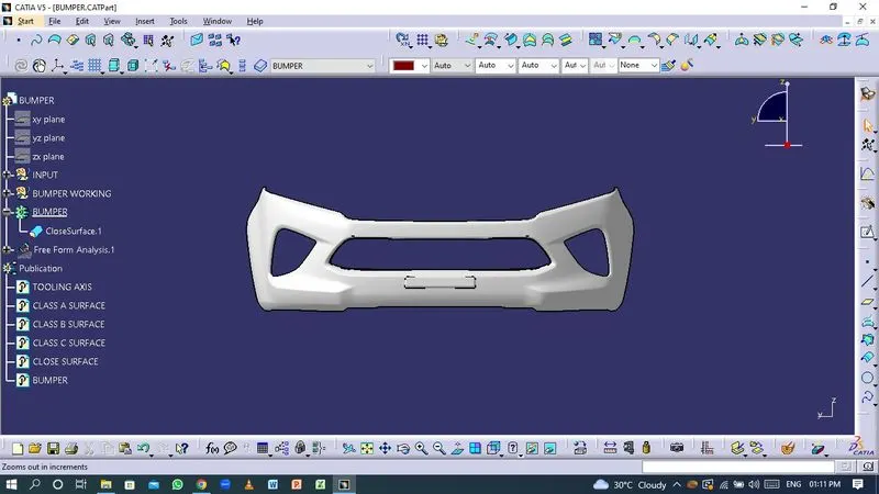
Draft Analysis
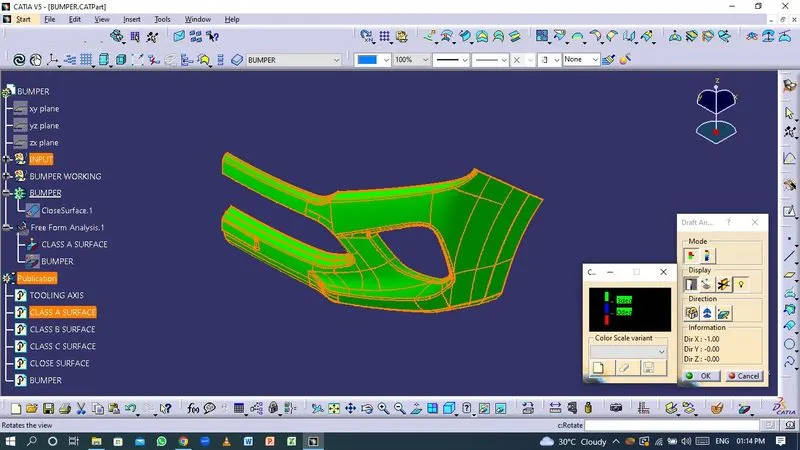
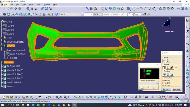
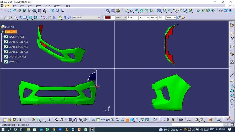
- The Draft Analysis command enables you to detect if the part you drafted will be easily removed. This type of analysis is performed based on color ranges identifying zones on the analysed element where the deviation from the draft direction at any point, corresponds to specified values.
- Most parts or applications require minimum of 1/2 to 1 degree, however 3 degrees is widely accepted as the norm.
- Draft analysis on Class-A surface.
- Draft analysis on final component.
Conclusion
Thus the Bumper Plastic component is created through the given Class-A surface with the required Draft angle using CATIA V5 software.