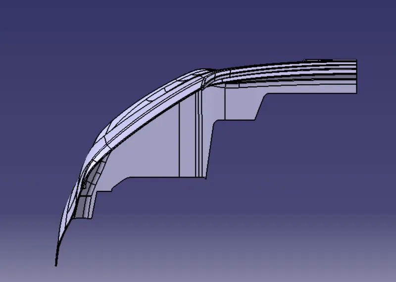
Week 8 - Challenge 4 - Bumper
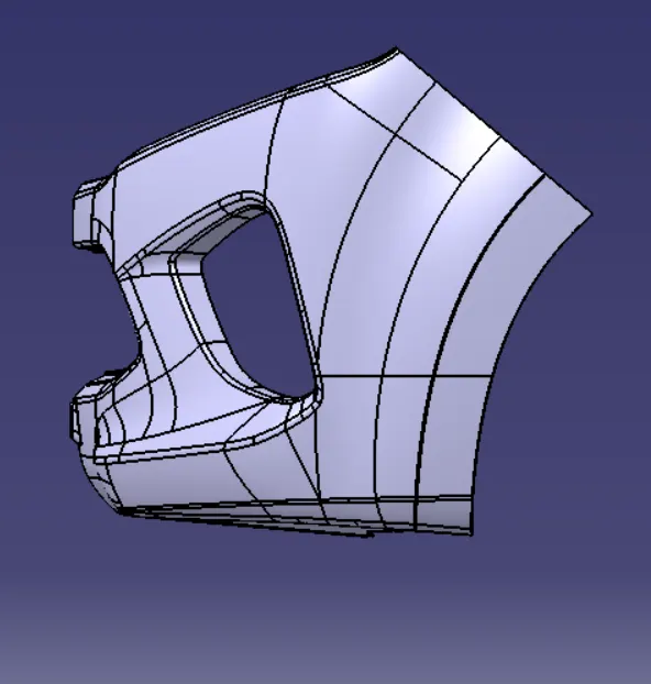
Visible surface is a Class-A surface. It provides the style team's look for the component, which the part design engineer uses to develop the component with all of the engineering requirements.
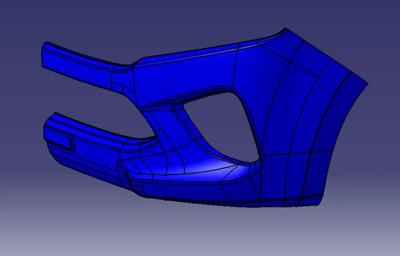
The class A surface's continuity must be verified first. In order to prevent gaps between surfaces, this is done. If any, we should address them right away.
- Class-A continuity check
- Analyze the class A surface through visual inspection.
To ensure that there is no space between them on the provided surface. With the use of the Join or boundary commands, we can additionally verify it.
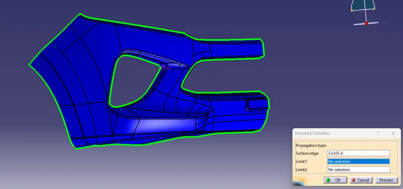
CREATION OF TOOLING AXIS
The opening and closure of the mold cavity and core during the component-making process are represented by the tooling axis. The best tooling direction should be taken into account by a plastic product designer in order to drastically reduce component costs.
The method is chosen to create the bumper's tooling axis-
1. Verify which tooling direction will work best on the given surface.
2. Cross-checking all three dimensions allows us to identify the ideal tooling direction.
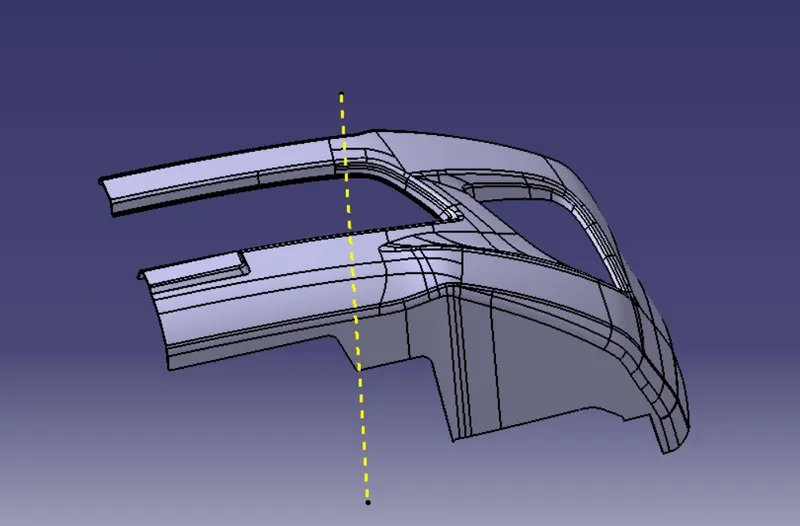
- Here, we learn that the x-axis direction is the optimal tooling direction for the pumper class-A surface.
- I first extract a surface and then make a midpoint on that surface in order to construct the tooling axis. At that point, an axis system was introduced.
Draft analysis for the given CLASS-A surface
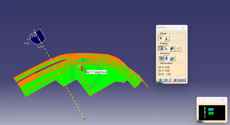
You can use the Draft Analysis command to determine whether the part you drafted will be simple to remove. In this kind of analysis, zones on the investigated element are identified by colour ranges where the deviation from the draft direction at any given place corresponds to predetermined values.
After choosing the tooling axis, draft analysis is carried out to see if the minimum draught (3 degrees) is being maintained.
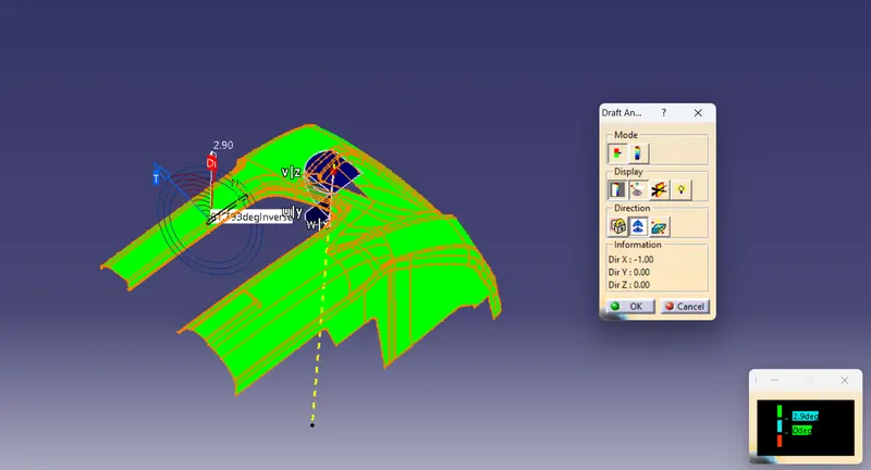
- The given A surface passes the draught analysis, and the green color indicates a suitable direction for further tooling.
- To view the draft analysis on each individual face, click on the analyses under the running point. When we change the cursor point, it indicates how much draft is on particular points.
Creating Class B Surface
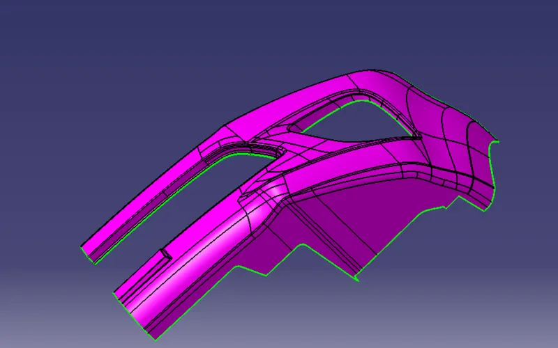
Class-B surface refers to a part's thickness that is both inside the part and not visible. In other words, a surface that is classified as Class B is one that is thinner than Class-A. This is the area of a model where the engineering components are located.
- Offset the class-A surface to a 3mm inward direction.
- Rework the offset surface s patches and discontinuities utilizing features like extrapolate, sweep, multi-extract, and multi-section surfaces.
- Check the boundary command to determine the border to ensure the Class-B surfaces are continuous.
- Hence class-B surface creation is done.
Creating Class C Surface
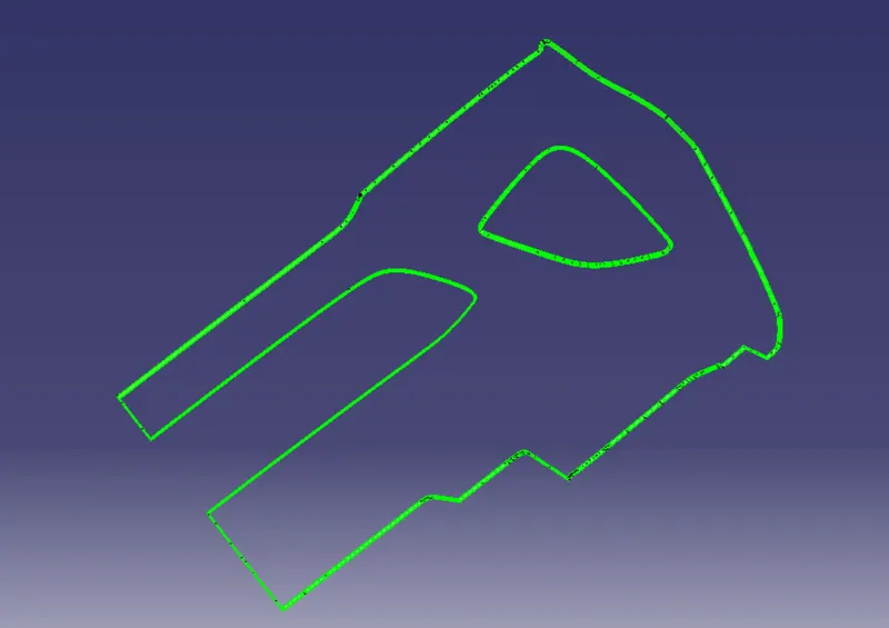
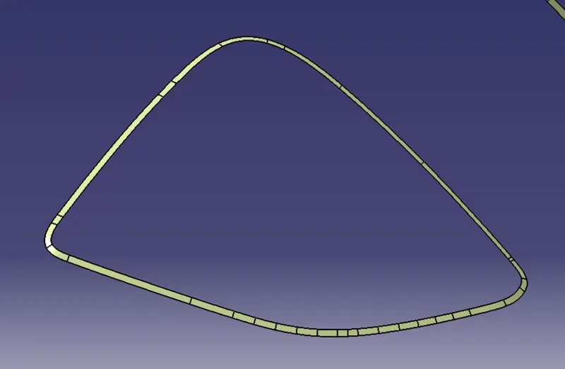
Class-C surfaces are the surfaces that connect class-A and class-b surfaces. Interior surfaces that are difficult to see or that will be covered by another item when assembled are frequently described as Class C surfaces.
We can't just make the class-A border curve and sweep it in one go because it's a complicated class-A surface. As a result, we must use the multi-extract command to make smaller curves, and we must then use the surface option to create a sweep of 90 degrees. To pass the draught analysis, sweeps at the middle of the bumper must have an 87-degree value.
Creating the final surface of the Bumper
- Join A and C Surface
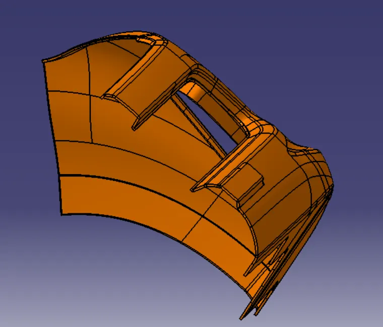
- Final Trim with B surface but first check there is no overlapping and gap between the surfaces by using the intersection command.
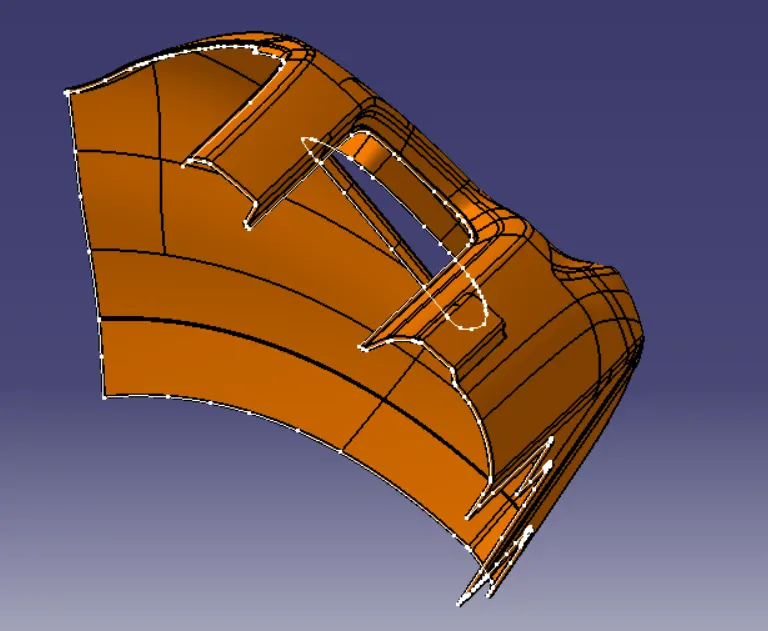
Final Surface before making it solid surface
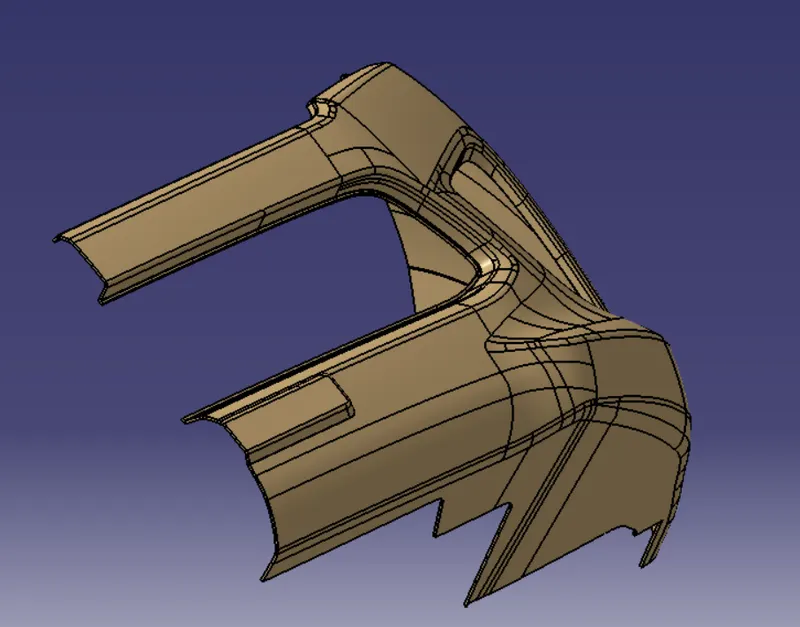
- Finally Using the thicken command to make our final plastic product of bumper.
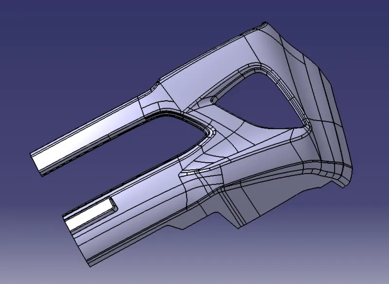
Draft analysis of the Final part body
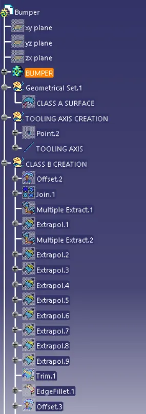
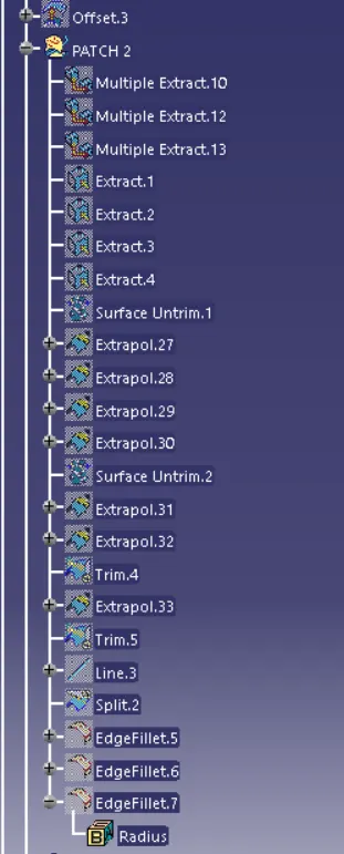
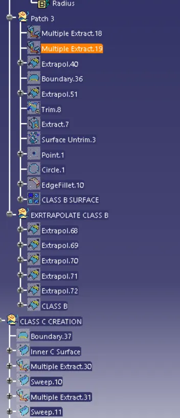
The expanded Tree Structure for the geometrical set and the Part Body
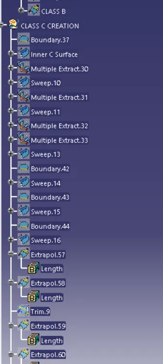
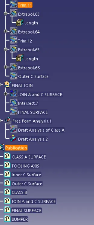
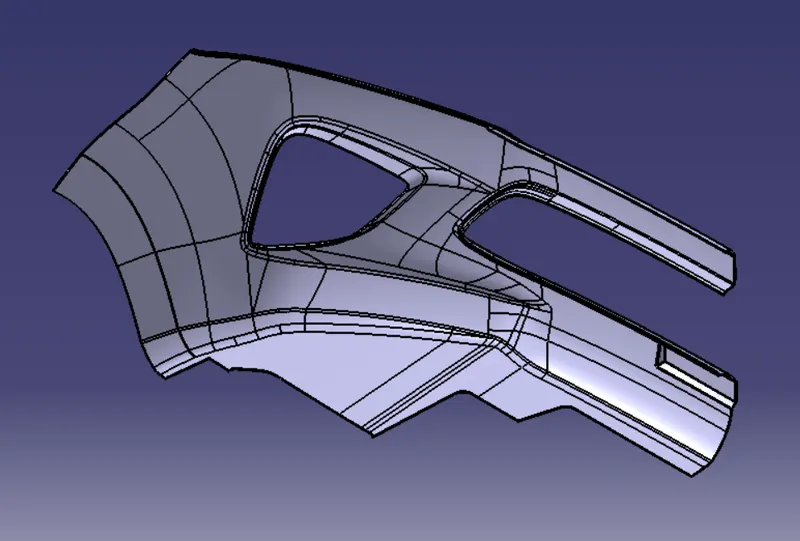
3D Part model in various orientations (Isometric, Front, Side, and Top View)
Isometric View
Front View
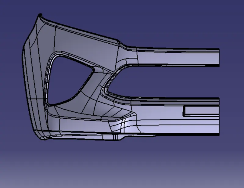
Side View
Top View