Week 8 - Challenge 4 - Bumper
AIM:- To Create the BUMPER Plastic component through the given Class-A surface. To begin with, the tooling axis for the given Class-A Surface should be created meeting the requirements of the draft angle and at the end perform the Draft analysis on the model. Take the Thickness of the component to be 3 mm
DESCRIPTION:
Class A surface: Class-A surfaces is a term used in most in automotive design to describe a set of freedom surfaces of high efficiency and quality.
Class B surface: Class B surfaces are the secondary surfaces that you can we see sometimes but are less important.
Class C surface: Class C surface are the surfaces which connects the class A and Class B surfaces.
Draft analysis: Draft analysis is performed on components where the ejection of materials happen after the material is made inside the tools.
OBJECTIVE:-
- Creation of Tooling Axis.
- Creation of class B and C surface.
- Creating a soild part out of surface modelling.
- Draft Analysis of class A Surface and final plastic component.
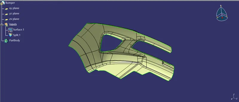
CLASS A:- Following Surface is given as the input for the component creation.
Creating of Tooling Axis:
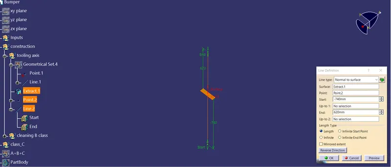
- Considering the Ejection from the cavity of the mould after manufacturing the interior trim (switch bezel) must have the nominal 3-degree draft angle.
- Hence the tooling direction is created by considering the above factor and bisecting method is used.
- The base surface of the class – A was extracted and a point at the centre is created and an axis system was inserted to the point with the current feature is disabled.
- Then, using project intersection along yz plane is created and the two inclined lines were drawn inside the positioned sketch.
- Then bisecting lines with the two inclined lines were drawn.
Creation of Class B Surface:
- For creating the class-B surface offset the class A surface to the given thickness 3 mm.
- Fill the gaps of the class B surface by using Sweep ar Mulit-section surface.
- Then all the surfaces have been extrapolated to get intersections between them.
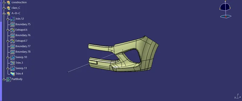
Creation of class c:
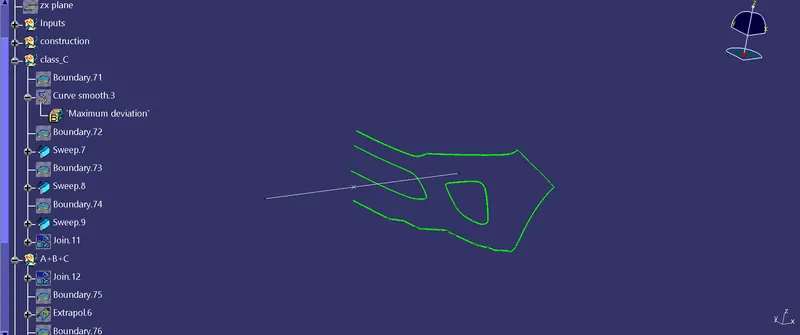
- Class C surface for this component is created using sweep command. All the ends of component surface was facing downwards, so the C surface will created perpendicular to B surface.
- To create C surface boundary of Class A surface and surfaces adjacent to boundary are extracted. Then sweep with reference surface commands is used and surface is created at 90 degrees.
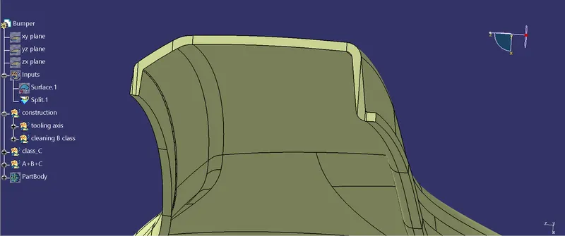
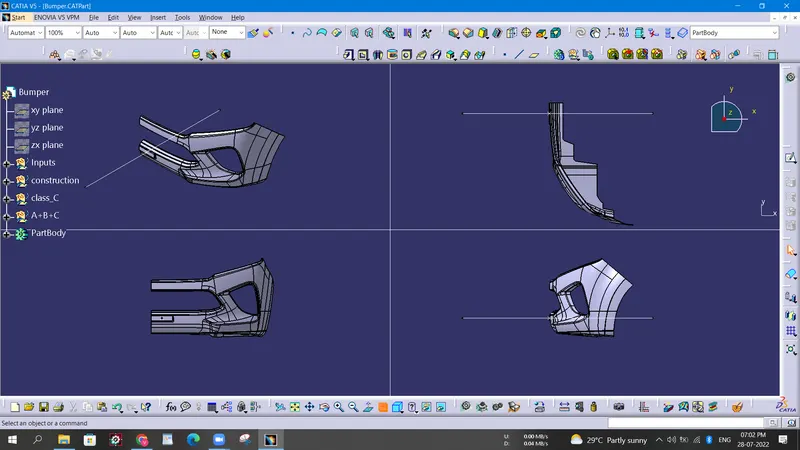
Class A + Class B + Class C
For this we have trimmed the join of the class A and class C Surfaces With the Class B.

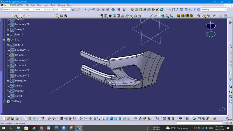
Draft Analysis:
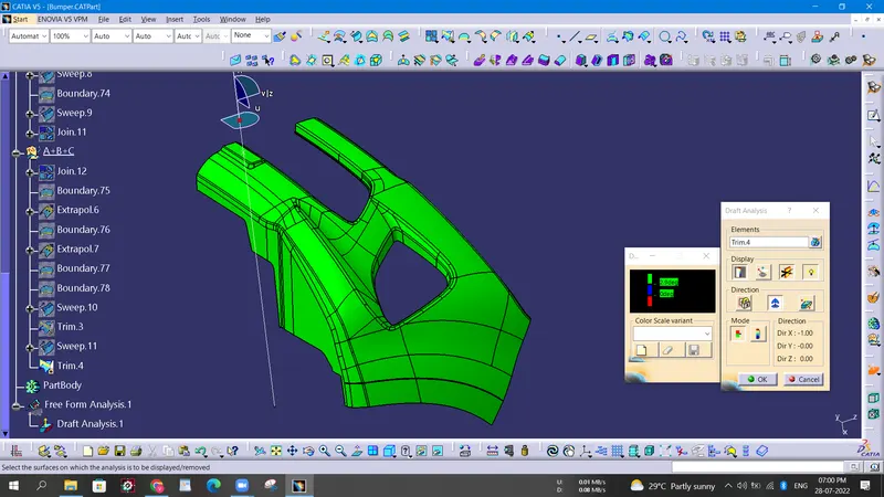
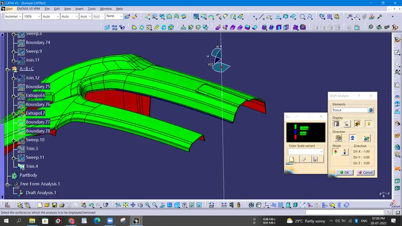
- First the class – A surface is checked before creating the Class –B&C surface and finally the solid body must be analysed. Both can be done by following the below procedures.
- By changing the view mode to custom view parameters – Material mode then the feature draft analysis is enabled.
- Then the compass was activated and placed with the tooling axis by dragging the red pointer and then locked it.
- Then, by selecting the quick analysis mode, the nominal value will be 3 degrees and checked for the component's draft angle.
- The green colour area shows that it satisfies the 3-degree draft angle. If not satisfied then by using the Running point tool the area is measured and then altered to get a successful draft for the created tooling direction.