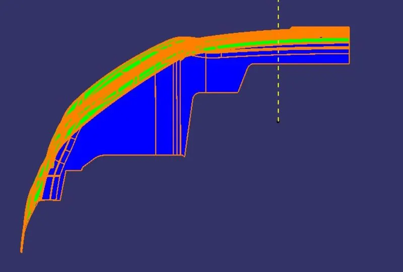
Week 8 - Challenge 4 - Bumper
AIM:--
Create the Bumper Plastic component through the given Class-A surface. To begin with, the tooling axis for the given Class-A Surface should be created meeting the requirements of the draft angle and at the end perform the Draft analysis on the model.
Take the Thickness of the component to be 3 mm
To be able to create solid from the given Class-A surface, by considering tooling axis and draft analysis.
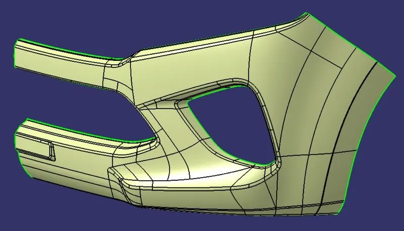
- The given Class-A surface:--
WHAT IS CLASS A SURFACE ?
It is an Asthetic surface and which is visible to the customers ie, Top surface,
- Tooling Axis:--
~ The tooling axis is the tool movement axis (core/cavity).
~ This axis will decide the draft direction.
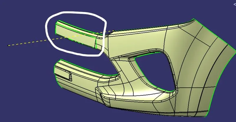
FIG:--EXTRACEDTHE SURFACE AND CREATED THE POINT AND CREATED THE TOOLING AXIS LINE.
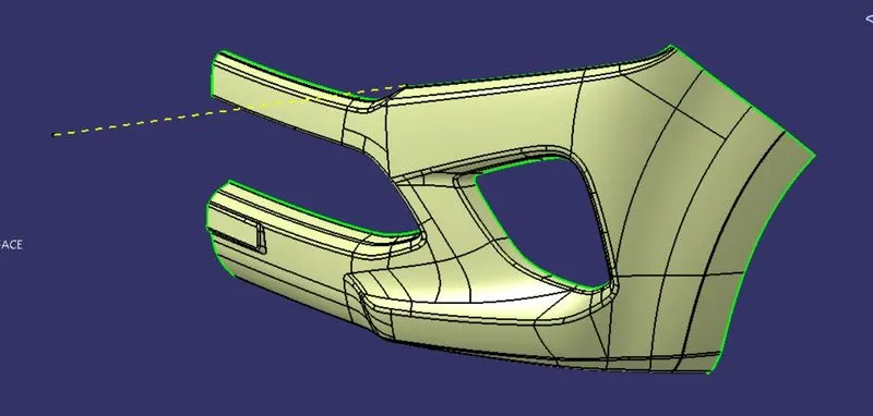
FIG:-- TOOLING AXIS
- Performing draft analysis on the given Class A Surface:--
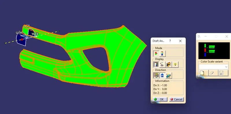
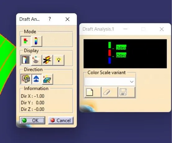
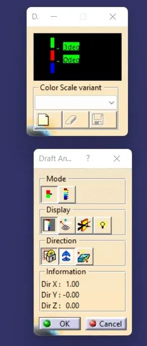
FIG:--The draft is considered as 3 degrees.
- THE CTREATION OF CLASS B SURFACE :--
WHAT IS CLASS B SURFACE ?
The surface which is thicken and applying the engineering features in it that sorface is called as CLASS B SURFACE
NOW OFFSET THE CLASS A SURFACE FOR 3mm IN INWARD DIRECTION.
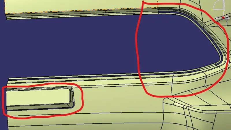
FIG:--THERE WILL BE GAPS IN THE FILLET AREAS AND USE MULTIPLE EXTRACT COMMAND AND SELECT THE SURFACE AND EXTRAPOLATE IT AND TRIM AND USE EDGE FILLET
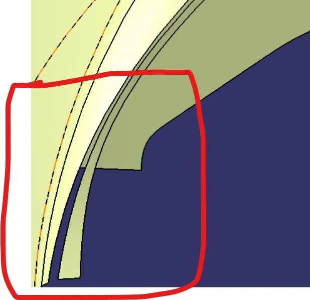
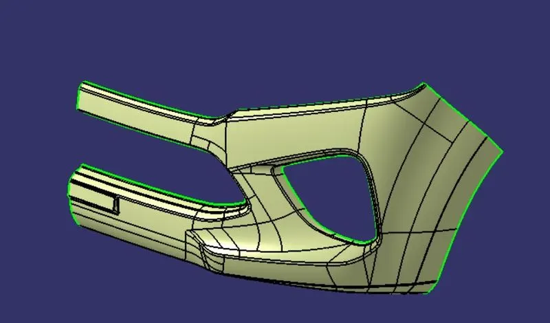
FIG:-- CLASS B SURFACE.
- THE CREATION OF CLASS C SURFACE:--
WHAT IS CLASS C SURFACE ?
The surface which joins the class A and B together that surface is called as CLASS C SURFACE .
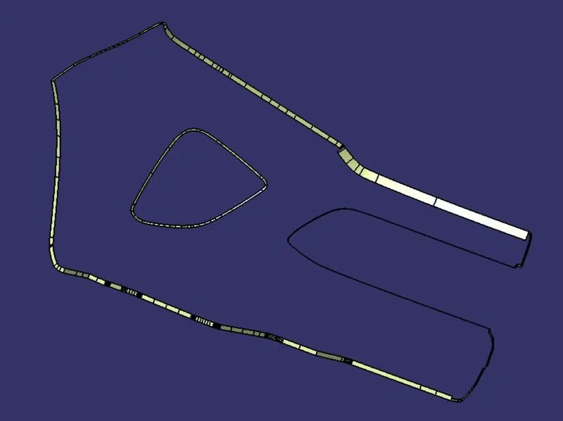
By using the MULTIPLE EXTRACT Command create a boundary and use SMOOTH CURVE Option to smooth the curve and use Sweep command to create a surface along "WITH REFRENCE SURFACE".
And the angle of draft given in Sweep is 90Degrees.
- NOW JOINING ALL THE THREE SURFACES :--
JOIN SURFACE A WITH SURFACE C :--
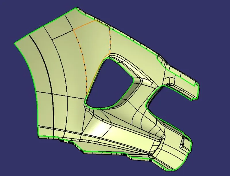
TRIM SURFACE AC WITH THE SURFACE B:--
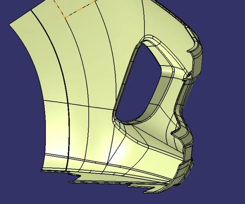
- NOW CREATING THE CLOSED SURFACE :--
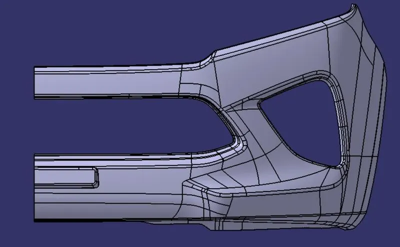
FIG:--The Solid is made by using the Close surface tool.
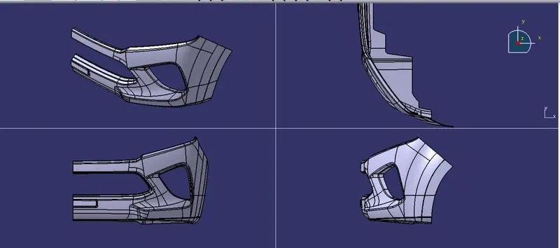
- PERFORMING DRAFT ANALYSIS FOR THE WHOLE BLOCK:--
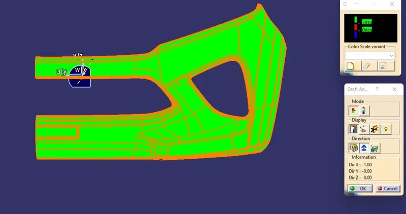
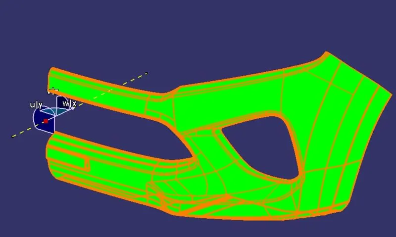
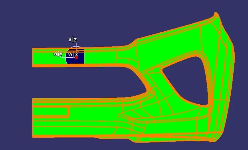
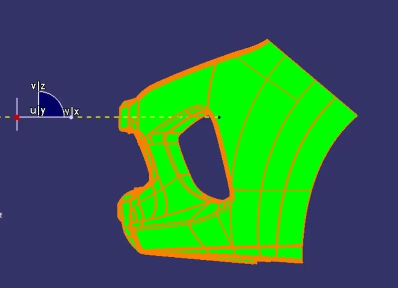
FIG:--Performed the draft analysis anf it had cleared the draft analysis for 3 degrees.
- Images of the color scale variant:--
- TREE STURCTURE:--
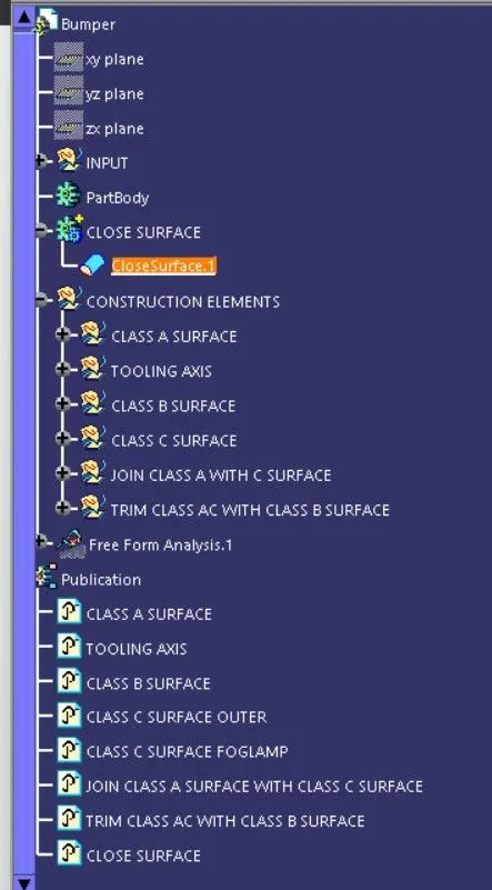
- Screenshots of the solid model with the proper color code of the draft angle in various orientations (Isometric, Front, Side, and Top View)
ISOMETRIC VIEW:--
FRONT VIEW:--
SIDE VIEW:--
TOP VIEW:--