Project 2 - Rankine cycle Simulator
~Aim :- Write a program to simulate the Rankine cycle
First we will see "What is Rankine cycle" is :-
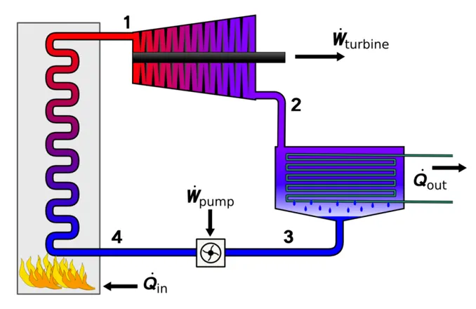
The Rankine cycle is an idealized thermodynamic cycle describing the process by which certain heat engines, such as steam turbines or reciprocating steam engines, allow mechanical work to be extracted from a fluid as it moves between a heat source and heat sink
--1-2:Isentropic compression in the pump
--2-3:Constant pressure heat addition in a boiler
--3-4:Isentropic expansion in a turbine
-- 4-1:Constant pressure heat rejection in a condenser
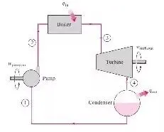
~The Rankine cycle can be understood better with its block diagram
~Code for Rankine cycle for a given Required Inputs:
Turbine Inlet temperature = 400° C
Turbine Inlet Pressure = 30 bars
Turbine Outlet Pressure = 0.05 bars = Condenser Inlet Pressure
Calculate the followings,
- Net work output
- Back work ratio
%code for Rankine cycle

clear all
close all
clc

%To print some data

fprintf("           Rankine cycle              \n")
fprintf("1-2:Isentropic compression in the pump\n")
fprintf("2-3:Constant pressure heat addition in a boiler\n")
fprintf("3-4:Isentropic expansion in a turbine\n")
fprintf("4-1:Constant pressure heat rejection in a condenser\n")

%Obtaining the input data
p1=input('Enter turbine inlet pressure ~');
T1=input('Enter turbine inlet temprature ~');
p2=input('Enter turbine outlet pressure ~');

%Extracting data

%state1
%extracting enthalphy at state 1
h1=XSteam('h_pT',p1,T1);
%extracting entrophy at state 1
s1 = XSteam('s_pT',p1,T1);

%state2
s2=s1;
%saturated liquid entrophy
sf2=XSteam('sL_p',p2);
%saturated vapour entrophy
sg2=XSteam('sV_p',p2);
x2=(s2-sf2)/(sg2-sf2);
hf2= XSteam('hL_p',p2);
hg2=XSteam('hV_p',p2);
h2=hf2+(x2*(hg2-hf2));

%state3
p3=p2;
s3=XSteam('sL_p',p3);
h3=XSteam('hL_p',p3);

%state4
s4=s3;
p4=p1;


%workdone by the turbine
wt=h1-h2;


%workdone to run a pump
v3=XSteam('vL_p',p3);
wp=v3*(p4-p3)*100;
h4=h3+wp;

%calculating net work
w_net=wt-wp;

%heat into the system
Qin=h1-h4;


%heat out from the system
Qout=h2-h3;

%To calculate Thermal efficiency
therm_efficiency=(w_net/Qin)*100;

%calculating work ratio
work_ratio=(w_net/wt);

%calculating back work ratio
back_work_ratio=(h1-h4)/(h2-h3);


%calculating temperature at the state points
T3=XSteam('Tsat_p',p3);
T2=T3;
Cp4=XSteam('Cp_ps',p4,s4);
Cv4=XSteam('Cv_ps',p4,s4);
k=Cp4/Cv4;
T4=T3/((p3/p4)^((k-1)/k));

%calulating temp,entrophy,enthalphy
T6=XSteam('Tsat_p',p1);
s5=XSteam('sL_p',p1);
s6=XSteam('sV_p',p1);
h5=XSteam('hL_p',p1);
h6=XSteam('hV_p',p1);
T5=T6;

%plotting the saturation curve
%temprature of water is=374
T=linspace(1,375,1000);

for i=1:length(T)
    sf(i)=XSteam('sL_T',T(i));
    sg(i)=XSteam('sV_T',T(i));
    hf(i)=XSteam('hL_T',T(i));
    hg(i)=XSteam('hV_T',T(i));
end

%displaying results
%state point 1
fprintf('At State point 1 \n')
fprintf('p1=%f bar\n',p1)
fprintf('T1=%f deg celsius\n',T1)
fprintf('h1=%f kJ/kg\n',h1)
fprintf('s1=%f kJ/kgk\n',s1)

fprintf('At State point 2 \n')
fprintf('p2=%f bar\n',p2)
fprintf('T2=%f deg celsius\n',T2)
fprintf('h2=%f kJ/kg\n',h2)
fprintf('s2=%f kJ/kgk\n',s2)

fprintf('At State point 3 \n')
fprintf('p3=%f bar\n',p3)
fprintf('T3=%f deg celsius\n',T3)
fprintf('h3=%f kJ/kg\n',h3)
fprintf('s3=%f kJ/kgk\n',s3)

fprintf('At State point 4 \n')
fprintf('p4=%f bar\n',p4)
fprintf('T4=%f deg celsius\n',T4)
fprintf('h4=%f kJ/kg\n',h4)
fprintf('s4=%f kJ/kgk\n',s4)

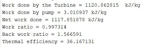
fprintf('Work done by the Turbine = %f  kJ/kg \n',wt)

fprintf('Work done by pump = %f kJ/kg \n',wp)

fprintf('Net work done = %f kJ/kg \n',w_net)

fprintf('Work ratio = %f \n',work_ratio)

fprintf('Back work ratio = %f \n',back_work_ratio)

fprintf('Thermal efficiency = %f \n',therm_efficiency)


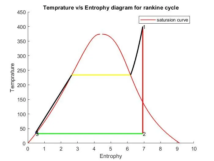
%plotting the T-S(Temprature v/s Entrophy) plot

figure(1)
hold on
plot(sf,T,'r','linewidth',1)
plot(sg,T,'r','linewidth',1)
plot([s1 s2],[T1 T2],'linewidth',2,'color','r')
plot([s2 s3],[T2 T3],'linewidth',2,'color','g')
plot([s3 s4],[T3 T4],'linewidth',2,'color','blue')
plot([s4 s5],[T4 T5],'linewidth',2,'color','black')
plot([s5 s6],[T5 T6],'linewidth',2,'color','y')
sc1=linspace(s6,s1,1000);
for l=1:length(sc1)
    Tc1(l)=XSteam('T_ps',p1,sc1(l));
end
plot(sc1,Tc1,'k','linewidth',2)


%Markings
text(s1,T1,'1')
text(s2,T2,'2')
text(s3,T3,'3')
text(s4,T4,'4')
title('Temprature v/s Entrophy diagram for rankine cycle')
xlabel('Entrophy')
ylabel('Temprature')
legend('saturaion curve')


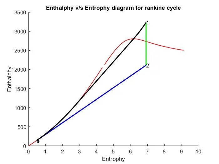
%plotting the H-S(Enthalphy v/s Entrophy) plot

figure(2)
hold on
plot(sf,hf,'r','linewidth',1)
plot(sg,hg,'r','linewidth',1)
plot([s1 s2],[h1 h2],'linewidth',2,'color','g')
plot([s2 s3],[h2 h3],'linewidth',2,'color','b')
plot([s3 s4],[h3 h4],'linewidth',2,'color','g')
hc=linspace(h4,h5,100);
for k=1:length(hc)
    sch(k)=XSteam('s_ph',p1,hc(k));
end
plot(sch,hc,'k','linewidth',2)
plot([s5 s6],[h5 h6],'k','linewidth',2)
for m=1:length(sc1)
    hc1(m)=XSteam('h_ps',p1,sc1(m));
end
plot(sc1,hc1,'k','linewidth',2)


%Markings
text(s1,h1,'1')
text(s2,h2,'2')
text(s3,h3,'3')
text(s4,h4,'4')
title('Enthalphy v/s Entrophy diagram for rankine cycle')
xlabel('Entrophy')
ylabel('Enthalphy')
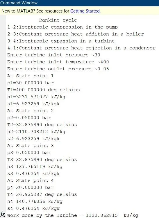
~Output for the code
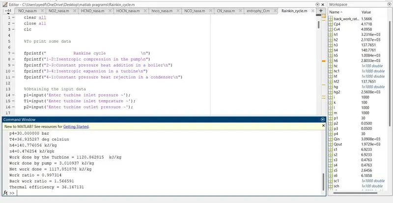
~Command window
~plot for Temprature v/s Entrophy
~Plot for Enthalphy v/s Entrophy
~Code Explanation
- Step1 - The XSteam data is used to extract steam and water properties of enthalphy,entrophy at specific pressure and tempratures
- Step2 - The inlet pressure,Turbine Inlet temperature and Turbine outlet pressure is given
- Step3 - With the help of these inputs we have to calculate the state points of Rankines cycle
- Step4- then we have to obtain the inputs
- Step5 - Then we have extract the data from the Xsteam data like h1=XSteam('h_pT',p1,T1)
- Step6-Then similarrly we have to extract data for entrophy
- Step 7- Then we have to calculate state points 2
- Step 8- Then we have to exctract saturated liquid entrophy and saturated vapour entrophy
- Step9-Simillarly we have to calculate the state point 3 and 4
- Step10 - we have a formula for workdone by the turbine ie,wt=h1-h2
- Step11- simillarly we know the formula for work done by the pump ie,wp=v3*(p4-p3)*100
- Step12- then we have to calculate the net work ie,W_net=wt-wp
- Step13- then the heat in to the system is Qin=h1-h4
- Step14- then the heat out from the system is Qout=h2-h3
- Step15- then we know the formula for thermal efficiency thermal eff=network/Qin *100
- Step16- then we have to calculate work ratio and back work ratio
- Step17- then we have to calculate temprature state points
- Step18- then we have to plot the temp V/S Entrophy and Enthlaphy V/S Entrophy diagrams
~Errors faced during coding
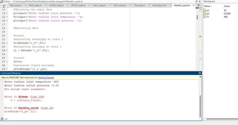
In The above Screen shot the error was in the line number 22 and the error was i had not used P1
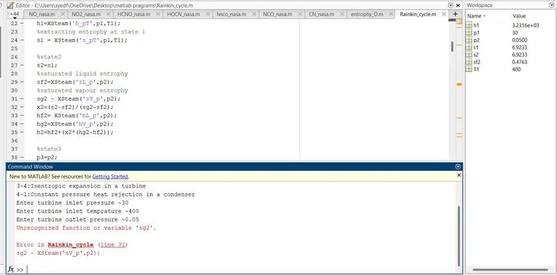
In the above screen shot the error was in the line number 31 and the error was instead of = i had used -
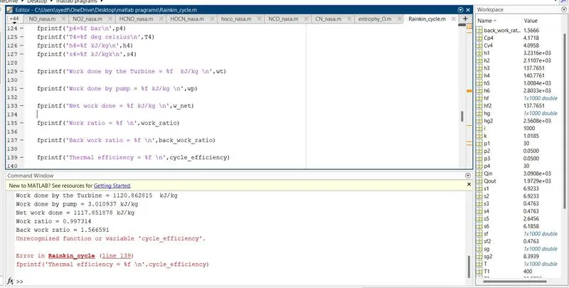
In the above screen shot the error was in the line number 139 and the error was instead therm_efficiency i had used Cycle_eff
~Reffrence
https://www.youtube.com/watch?v=4Ts5Hbu7cGg
https://en.wikipedia.org/wiki/Rankine_cycle
link for XSteam data file
https://drive.google.com/file/d/1RK_fvrOj38CIaQvmLT1S3daqHnxKCGU-/view