Week 8 - Challenge 4 - Bumper
CREATION AND EXECUTION OF TOOLING AXIS, DRAFT ANALYSIS FOR PLASTIC COMPONENT (BUMPER)
OBJECTIVE:
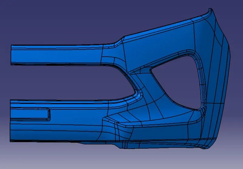
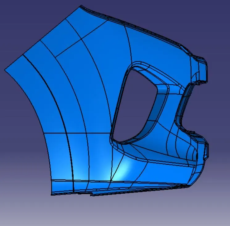
The main objective is to create a tooling axis and draft analysis for the plastic component design using CATIA V5. The design of plastic surfaces includes CLASS A SURFACE, CLASS B SURFACE and CLASS C SURFACE. Combination of these three includes the Solid conversion of plastic components.
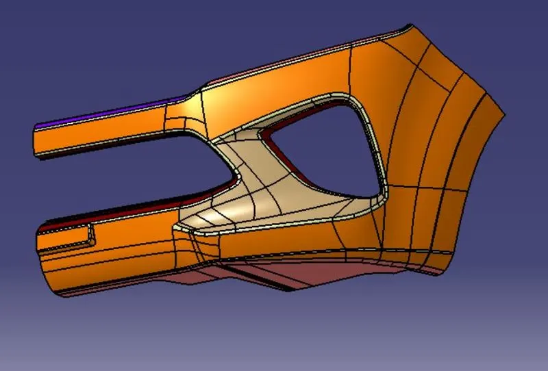
TOOLING AXIS: It is the area where the direction in which the mould open.
STEPS TO BE FOLLOWED ARE;
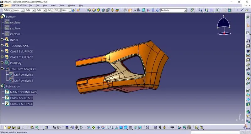
STEP 01 – CLASS A SURFACE INSERT
Insert a basic component like no thickness element into catia v5 and name it as Class A surface and check for the boundary condition. The boundary condition is used to identify the continuity of the component.
STEP 02 – MAIN TOOLING AXIS CREATION
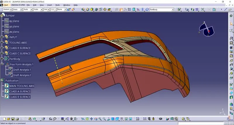
After this steps make the point on the base surface and make the axis coordinate with the help of point. Now make the line that passes through the point and the base surface as reference, these line is called as main tooling axis.
STEP 03 – DRAFT ANALYSIS
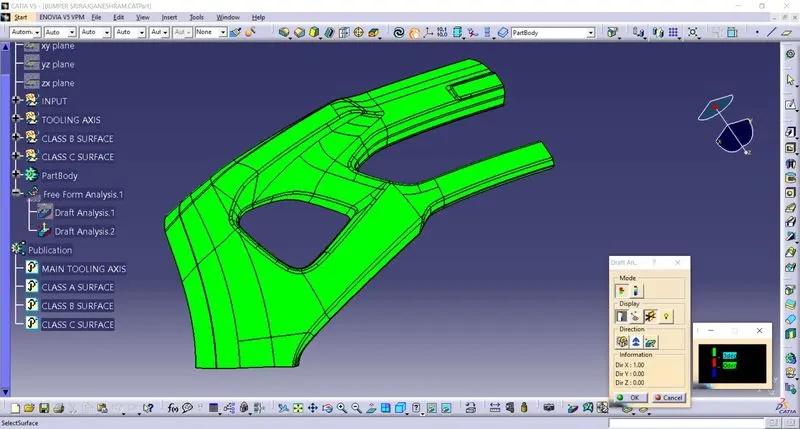
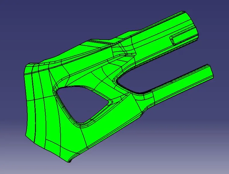
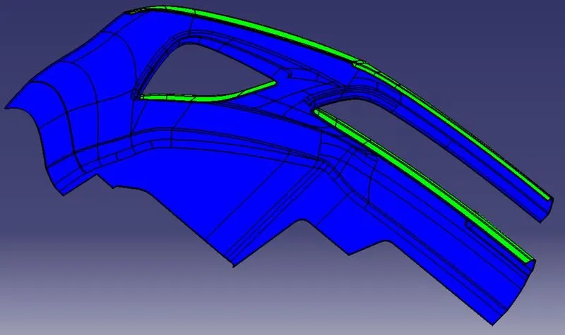
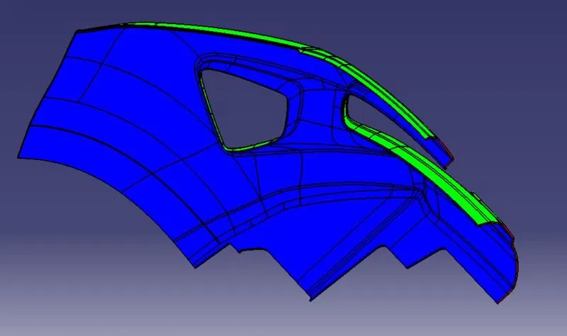
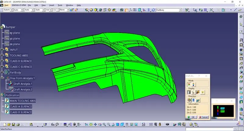
By using draft analysis we may find the draft angle is maintaining at 3 degree or not. By using draft analysis symbol in catia open the tool box and insert the compass into the main tooling axis and check the draft angle deviation by using the analysis check point option and finally select the object where the analysis takes place. Now the analysis part area may change into green colour and below of that green it may appear like blue it indicates it is a negative value.
STEP 04 – PUBLICATION
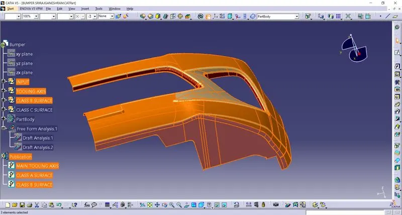
Publication is to publish the main things into a separate tree structure. Is used to maintain the things as highlighted while designing.
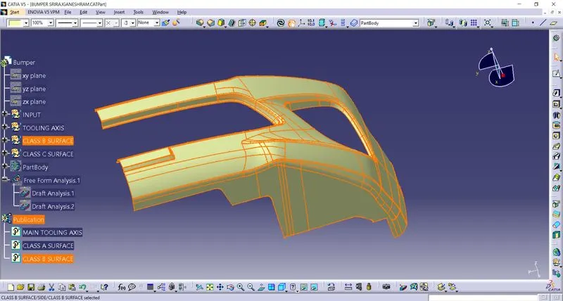
STEP 05 – CREATING CLASS B SURFACE
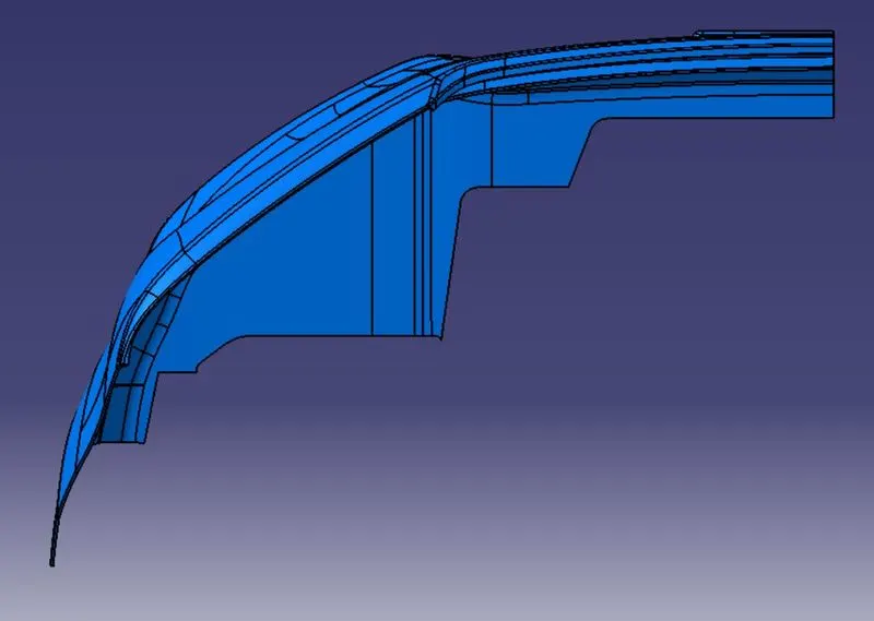
Class B surface is the extraction of shape and structure from class A with the help of surface shape features with the deviation of 2.5mm difference between the class A and B surface. By using the extract tool feature this can be achieved by using step by step. (Make the outer wall of the component as much careful with inward offset of 2.5 mm and combine with the class A surface in every corner)
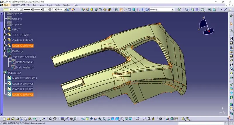
STEP 06 – CREATING CLASS C SURFACE
Class C surface is the parallel wall thickness of the tooling axis. It also created by using the class A surface boundary area and surface as refernce. Now make the sweep option with surface option and make the surface with perpendicular as gemotry. Then the sweep option is used to create a wall thick by using 90degree deviation angle as shape and it must be facing inward as direction.
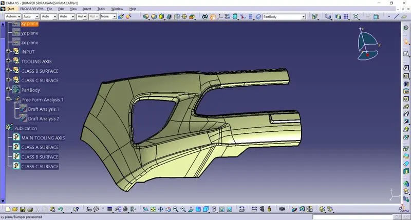
STEP 07 – COMBINE OF CLASS A, B AND C SURFACES
Final step of the surface create is combination of A, B and C surfaces. Now make the trim one by one from A and B surface and remove unwanted areas from the respective surfaces. After all this join the trimmed surfaces into one form with the help of join option and name it as final surface.
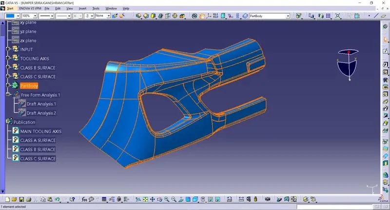
STEP 08 – CONVERT TO SOLID
Now convert the surface to solid form by using close surface option in a new body.
STEP 09 – DRAFT ANALYSIS OR FINAL SOLID PART.
Repeat the same draft analysis procedure from surface and make sure that the solid part may take the same draft compared to class A surface.