Design of American chopper and its components with photorealistic rendering by using Solidworks
Design of American chopper and its components with photorealistic rendering by using Solidworks
Objective:
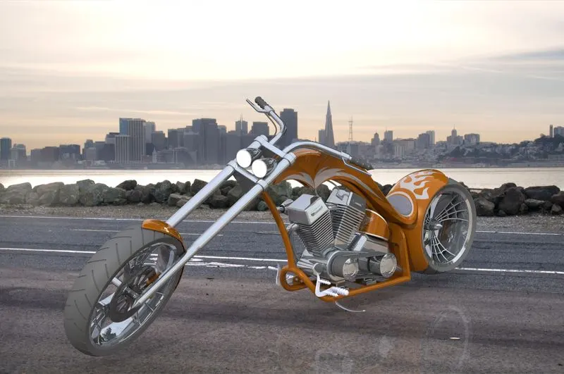
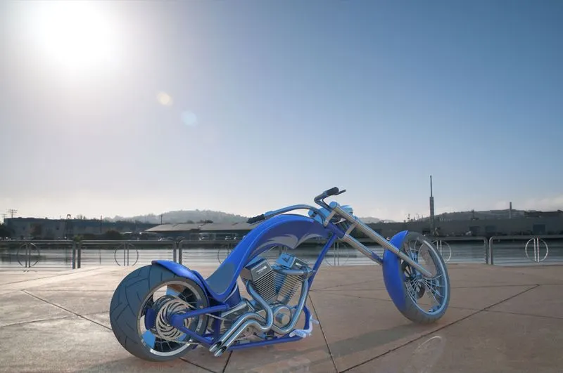
Main objective of the project is to design and assembly of American chopper parts in Solidworks 2020 with exact photo realistic rendering using photovie-360. Renders can be done by using decals, cameras, lighting and environment setups.
Introduction:
The project is about to achieve a chopper assembly with the help of chopper image by using non-parametric method of approach. There are two types of approach while going to design a component.
- Parametric model approach.
In this approach model is going to design with exact dimensions to fit their purpose in real time usage. Normally this method is used for manufacturing purpose.
- Non-Parametric model approach.
In this approach design is purely focus on shape and aesthetic look of a component. Normally this type is used for viewing and presenting a model structure purpose only.
While going to design a part there is different steps to focus. They are
- Observe the part structure
- Identify where and how to start
- Make each and every area to be fully constrained
- Aesthetic approach of the component
- Application viewing.
Solid Works 2020.
These software is used to generate a component by using various features and methods. Some of the important tools are listed as follws.
For Design:
- Sketch setup
It consists of line, circle, rectangle, sketch pattern, convert & trim entities, smart dimensions, etc...
- Features
It consists of two types. They are
Solid feature:
These type of feature is used to make a material filled components which are going to take place in real time application. The solid features are extruded boss, revolved boss, rib, draft, shell, etc…
Surface Feature:
These type is normally called as zero thickness method. The tools used to achieve surface types are extruded surface, revolved surface, lofted surface, Boundary surface, etc…
For Assembly:
- Mates
- View setup
Design Methodology:
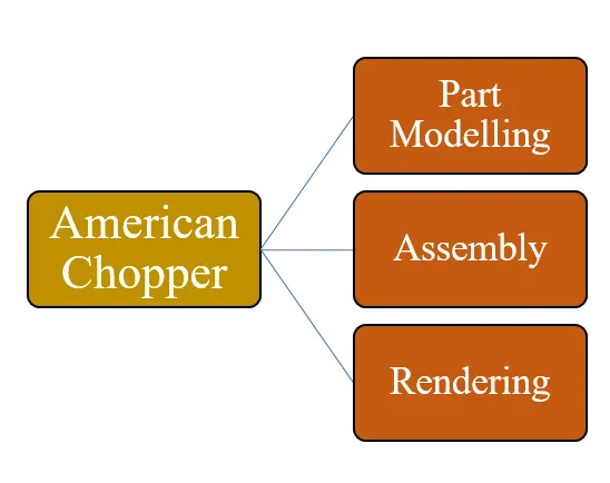
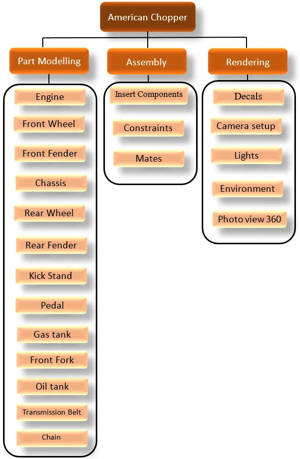
Overall design process is showed in a below flowchart.
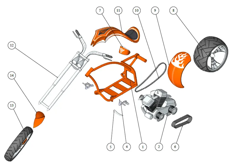
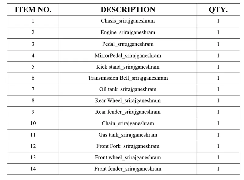
Exploded View & BOM:
Description:
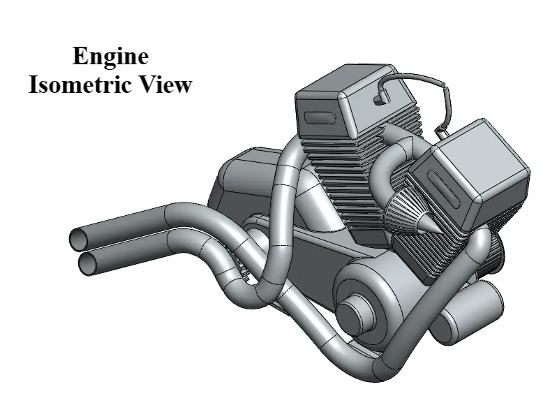
- Engine
Device used to convert the energy into rotary motion with the help of heat source.
Sketch tools:
- Insert picture
- Line
- Circle
- Splines
- 3 point arc
- Trim and extend entities
Features:
- Boss extrude
- Fillet
- Plane
- Revolve
- Circular pattern
- Extruded cut
- Chamfer
- Sweep
- Mirror
- Combine
- Projected curves
- Split
- Fillet
- Dome
- Applying Appearance
Appearance:
Chrome Steel
Steps involved:
Select the plane and insert the chopper image by using sketch picture setup. By using this picture draw the initial centre line and draw the circle matching as it is like image and join the circles by using line command. Then extrude the needed area by sing extrude mid plane option.
Then remove the material by using circle option with the help of circular pattern.
Now start the cylinder area by sing extrude feature with draft value to get required shape and use the mirror option to get another cylinder profile with the help of plane. By using extruded cut feature make the required number of cooling fin features with the help of linear pattern.
For exhaust pipes use splines and projected curves tools to achieve exact shape and by using sweep option make the required material formation. In sweep option use the circle and projected curve option to form material with the help of pierce constrain.
Finally apply the appearance for every bodies as chrome steel.
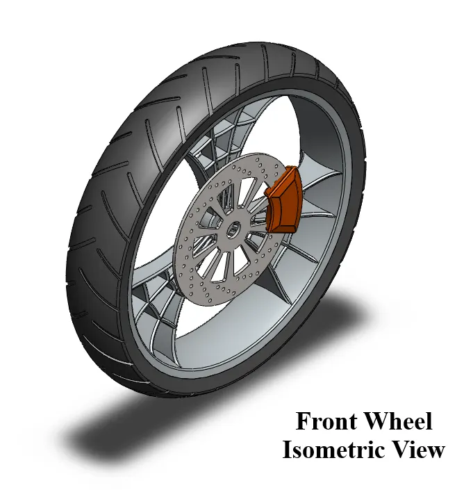
- Front Wheel
The component used to transfer the object from one place to other. The movements are controlled by using brakes.
Sketch tools:
- Line
- Circle
- Arc
- Splines
- Trim, extent and convert entities
- Sketch mirror
- Trim
- Offset entities
- Fillets
Features:
- Extrude boss/base
- Extrude cut
- Revolve
- Circular pattern
- Revolve cut
- Fillet
- Combine
Appearance:
Chrome steel, carbon steel, painted Siena, Matte rubber
Steps involved
By sing the semi sphere with the help of revolve option make the outer area by sing exact axis reference.
Now the inner aesthetic area called as spider web is drawn by sing splines and 3 point arc option. Then the excess lines are removed by using trim entities.
Then extrude the sketch with mid plane option and make the spider web profile and go with the fillet option where ever needs. Finally using the circular pattern option to make the spider web profile filled in the wheel numbered as 3.
Now use 2 circle option and add lines to create a calliper and extrude the option. By making fillet and chamfer option for exact look of calliper.
With help of rim structure use convert entities option and fill the profile as like tyre and make revolve option. Now use the extruded cut with some angle lines to create a gripper profile and pattern with the help of axis.
Now add the appearance of the bodies with their usage and looks.
- Rim – Chrome steel
- Rotor – Carbon steel
- Calliper – Painted Siena
- Tyre – Matte rubber
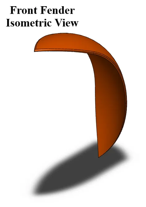
- Front Fender
Fender are used to cover the tyre to prevent vehicles from mud, sand, etc…
Sketch tools:
- Line
- Circle
- 3 point arc
- Trim
- Extend entities
- Splines
- Off set
Features:
- Reference Axis
- Revolve
- Split
- Fillet
Appearance:
Painted Siena
Steps involved:
By using the 3 point arc tool form an arc at required dimensions and make the edges as horizontal as possible.
With the help of offset entities make the sketch into closed profiles and the extra lines are trimmed.
By using the revolve option make the required angle of material with the help of reference axis.
Now the front and rear side of the fender is cut by using splines option and make the sharp edges are round profile with the help of fillet.
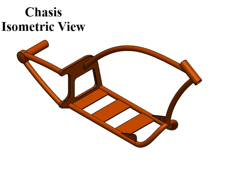
- Chassis
The basic skeleton structure of the vehicle. Each and every parts should be fitted with the help of Chassis. Normally chassis is made of steels pipes with bending and welding operations.
Sketch tools:
- Line
- Splines
- Circle
- Sketch picture
- Arc
- Trim entities
Features
- Boss extrude
- Extruded cut
- Sweep
- Mirror
- Chamfer
- Fillet
- Dome
- Split
- Combine
- Projected curves
- Revolve
Appearance:
Painted Siena
Steps involved:
Insert the chopper reference picture by using sketch picture command and make sure the values entered for fixing the picture as needed.
By using the circle tools start the initial first step of the chassis. Then the splines are drawn in between the connected points. If the splines are need in the next plane use the projected curve option to form a splines that intersect between two faces.
Use sweep option to form a material by using the help of two sketches one is circle and other one is projected curves.
Now draw the rectangle in front view option and use extrude features to make the flat face for engine mounting.
Make extrude for the kickstand and pedal mounting with exact triangle shape.
By using split feature remove the unwanted and extra area of the pipe structure and use fillet and chamfer option where ever needed.
Finally use the revolve option to form front fork provision and make the split option to remove the unwanted pipe sections inside revolve feature.
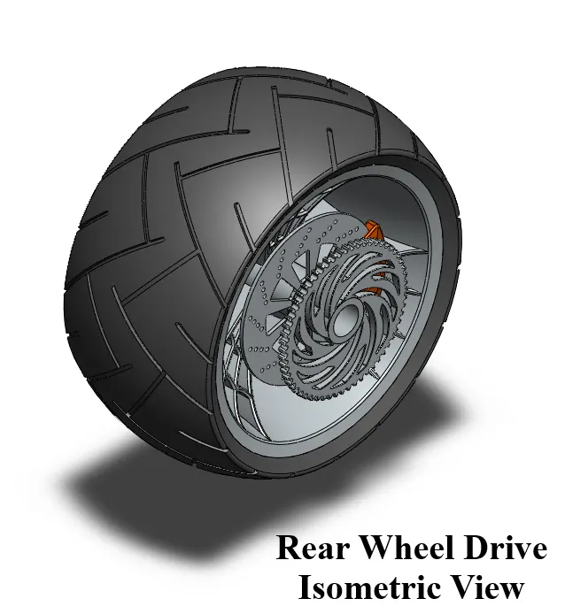
- Rear Wheel
Rear wheels are main drive system in vehicle principle. Normally the power that is generated from the engine to be transferred into rear wheel drive only with help of chain.
Sketch tools:
- Line
- 3 point arc
- Splines
- Circles
- Fillet
- Convert and trim entities
- Sketch mirror
- Offset
- Trim
Features:
- Extruded boss
- Revolve
- Extrude cut
- Pattern
- Combine
- Revolve cut
- Fillet
Appearance:
Chrome steel, carbon steel, painted Siena, Matte rubber
Steps involved:
The rear wheel drive consists of five bodies’ creation while designing. They are
- Rim
Draw an arc with proper profile fillet at both sides and use the revolve option to form the basic rim with help of centre axis.
By using spline option form a spider web design in front plane and make mirror to create same as other side. Use trim and extend entities to add and removed unwanted lines. Now make the extrude option in mid plane position. Use circular pattern option make the 3 web design with 3 equal instants.
- Rotor
Draw a circle in the front plane for outer profile, now make a small circle at inside the big one make linear pattern to create heat dissipation provisions.
Now extrude the circle option to make the rotor sketch into material form.
- Calliper
Make two circles on the faces of the rotor and connected by using line option.
Now make extrude of these sketches and use chamfer features to make clear profile of calliper.
- Sprocket
Draw the circle facing front of calliper and extrude. Make the sketches inside of extrude with the help of splines and make a profile. Now cut the profile and make the circular pattern to fill all over the circle material area.
- Tire
In right plane use the revolve option with help of convert entities and mirror tool form a sketch like semi sphere.
Now draw the rectangle profile and make the profiles are in different angles and use extruded cut option with the help of up to surface option.
Now use the circular pattern form a profile cut over circular profile of the tyre.
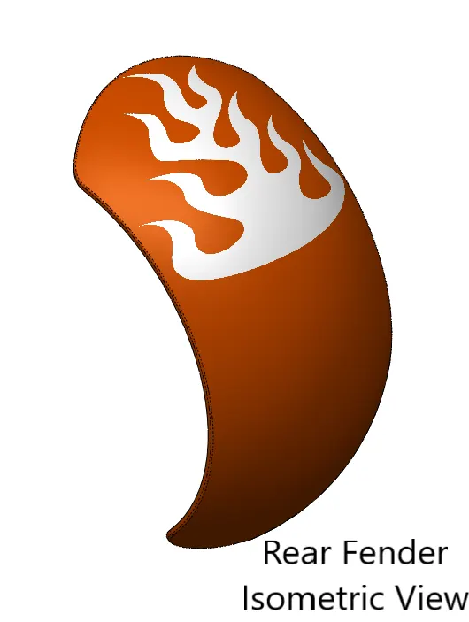
- Rear Fender
Sketch tools:
- Lines
- 3 point arc
- Offset entities
- Trim entities
- Extend
- Splines
Features
- Revolve
- Axis
- Fillet
- Shell
Appearance:
Painted Siena
Steps involved:
By using arc tool form a sketch and make sure that the both edges are in horizontal format.
Make the sketch drawn are in offset at a certain amount distance then the unwanted area are removed by using trim entities.
Make one reference axis for revolve the component at both directions.
Use fillet where ever needed mostly at the edges of the profile.
Finally use the shell option to make the part into thin form.
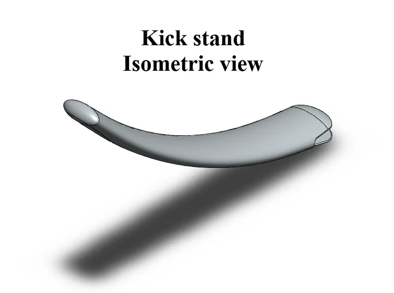
- Kick Stand
The component is used to hang the overall structure at some angle of inclination. Normally made up of hollow pipes.
Sketch tools:
- Lines
- Splines
- Circle
- Ellipse
- Trim
Features:
- Loft
- Extruded cut
- Plane
- Dome
- Split
- Fillet
Appearance:
Chrome steel
Steps involved:
Draw the ellipse in the proper plane and form another plane with help of reference geometry option and form a small ellipse profile compared to first one.
By using the loft option make the material in between the two ellipse with the required angle.
Then remove the material that is not necessary in the profile. For the fixing area draw the rectangle and make cut extrude and form a circle to form a proper profile inside the cut area.
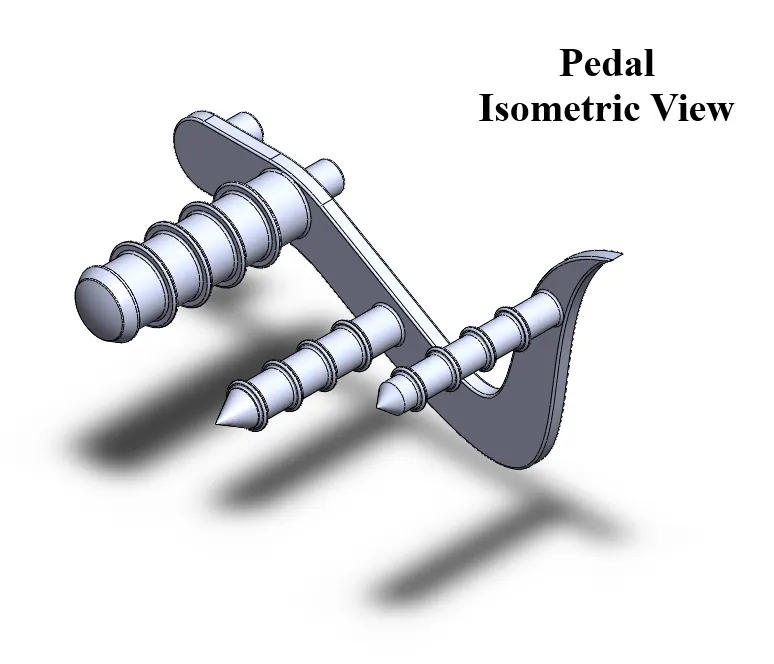
- Pedal
Used to actuate the gear at the time of running by accessing at certain up and down position.
Sketch tools:
- Line
- Circle
- Splines
- Fillet
Features:
- Extrude boss
- Fillet
- Chamfer
- Revolve
- Pattern
Appearance:
Chrome steel
Steps involved:
Draw the circle extend the line and make the profile with the help of splines and make the profile complete.
Extrude the sketch in one direction.
Draw the profile like rectangle and revolve the sketch using reference axis. Add the dome at the front side of the rectangle.
Draw the circle like profile and extrude the circle and add fillet and both edges and pattern all the features with required dimensions.
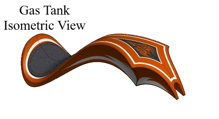
- Gas Tank
This tank is mostly used for storage of fuels. Always placed above the engine for fuel delivery.
Sketch tools:
- Lines
- Splines
- Insert picture
- Offset and covert entities
- Offset
- Arc
- Trim
Features:
- Sweep surface
- Trim surface
- Projected curves
- Boundary surface
- Surface loft
- Knit
- Split lines
- Fillet
- Sweep cut
- Shell
- Mirror
Appearance:
Painted Siena
Matte rubber
Steps involved:
Insert the image using sketch picture option in the correct plane. Draw spline curves traced by the picture and complete.
Make the swept surface where feature to make surface material addition with proper angle. Then the extra areas are cut by using trim surface.
By using different plane setup draw the front side of the tank and make surface using loft surface feature. Now draw the projected curve and make the surface by using boundary surface option.
Now mirror the features and form full tank view. By using knit surface feature combine all the separate feature into one.
Then make the seat provision at the rear side of the gas tank with the help of extrude feature. Add the bottom surface into closed area with the help of surface boundary and loft option.
Now make the shell option to make hollow inside tank area.
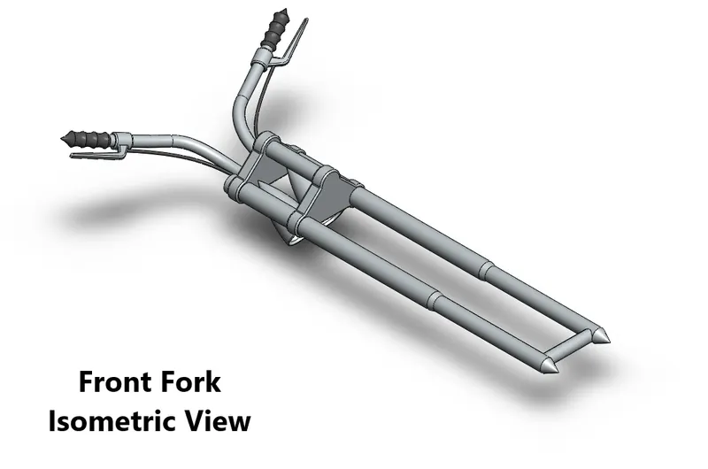
- Front Fork
Fork is used to control the total vehicle direction at the time of driving. Normally fork holds the front wheel drive.
Sketch tools:
- Line
- Splines
- Circle
- Trim entities
- Convert entities
- Planes
Features:
- Revolve
- Extrude
- Fillet
- Pattern
- Dome
- Sweep
- Mirror
- Combine
Appearance:
Chrome steel
Steps involved:
Draw rectangle shape in a vertical plane and make sure that bottom area looks like sharp edge and by using revolve option make the sketch into solid form.
By selecting the top fork area draw the sketch and make extrude. Make the fillet where sharp edges to be removed. Finally make the linear pattern option and make other one extrude feature.
Do rectangle at bottom and revolve the sketch to form the front wheel mounting area.
Now draw the semi-circle structure to form a front light area by sing revolve feature. By using dome option make the front area into light structure.
By using sweep option make handle bar area with the help of circle and path. Now revolve comment is used make the handle structure with some fillet features.
Make the mirror option and select all the bodies into mirror form.
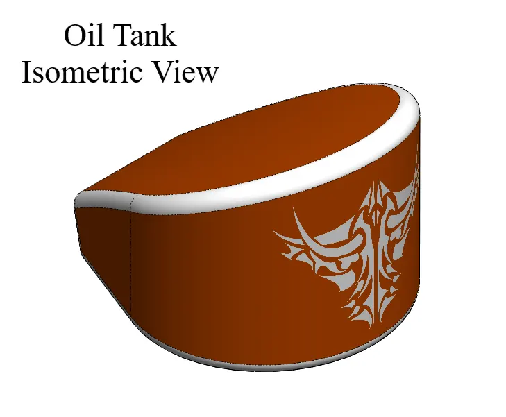
- Oil tank
The container is placed in between the engine and gas tank. These containers are normally used to store the fuel and deliver to the engine when needs.
Sketch tools:
- Line
- Splines
- Offset and trim entities
Features:
- Extrude
- Combine
- Fillet
- Shell
Appearance:
Painted Siena
Steps involved:
Draw profile in a top plane and extrude it. Now draw the sketch at the right plane and extrude it at horizontal reference and make extrude in mid plane format.
By using combine option make the exact required surface with auto trim option with the help of two extrude feature.
Make the fillet at the top and bottom edge of the tank. Finally make the shell feature to form a hollow structure.
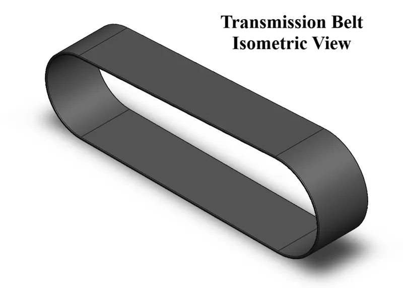
- Transmission Belt
The power from one area to other is transmitted by using belt drives in case of short distance. Normally belts are not used to transfer the higher transfer rate due to its slip factor.
Sketch tools:
- Line
- Arc
- Offset and trim entities
- Plane
Features:
- Extrude
- Fillet
Appearance:
Matte rubber
Steps involved:
By selecting the front plane option draw two circles with some instant dimensions. By using line command draw the line at both circles tangent constraint point.
Trim the unwanted circles and make the sketch into fully defined form. Now make the offset option to make the sketch into some instant inside area.
By using the extrude option make the belt width by adding material. Finally use fillet option to make the round structure.
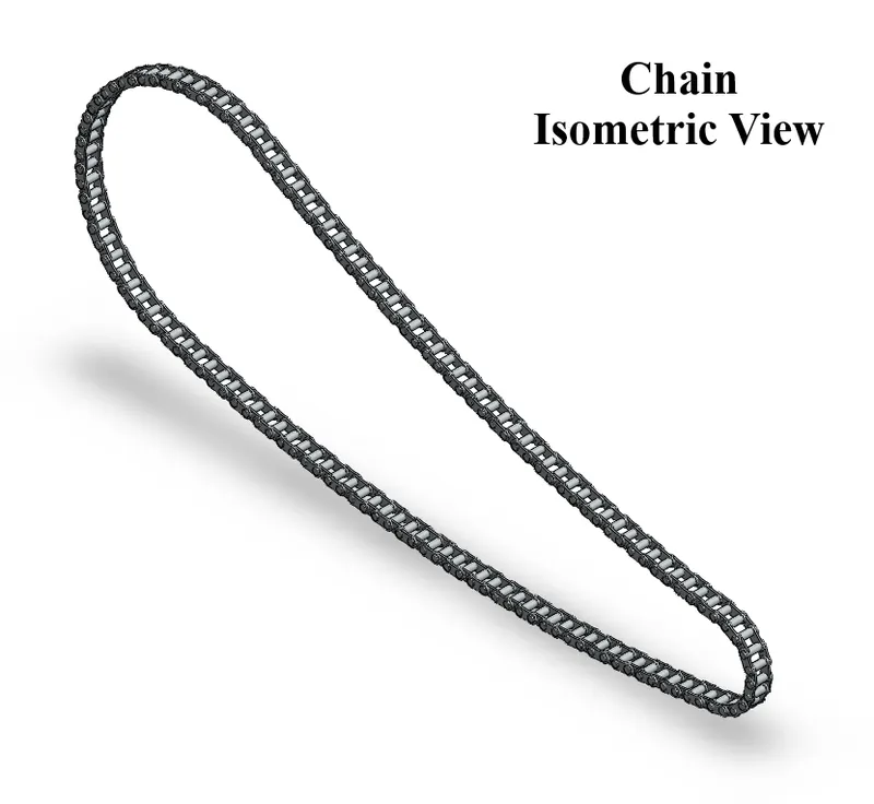
- Chain
The multiple joints of pins and connectors are called chains. Normally chain drive are used to transfer the power from one to other. These chain drives are transfer the power at exact rate with minor slip factor.
Sketch tools:
- Lines
- Circles
- Arc trim entities
- Block
- Save block
Features:
- Extrude
- Chain driven pattern
- Mirror
- Fillet
Appearance:
Chrome steel
Steps involved:
Draw the circles at the front plane and connect the circles by using line tool. Like this want to do both the connectors of chains.
Now using make block option create the block of both connector into block form. Then save the block and insert back into plane.
Using extrude option add the material of both connector and chain into solid form. Now make the chain and connector into filled form in the reference circle by using circular driven pattern.
If any instant are overlapping make the correction manually to fill the connector and chain in a correct path.
Assembly:
Two or more components are connected with their application purpose is called assembly. Normally assembles are made by using lot of constraints. Three proper constraints are most enough to make two components into assembled form.
Types of mates are,
- Coincident
- Parallel
- Perpendicular
- Tangent
- Concentric
- Lock
- Symmetric
- Width
- Cam
- Slot
- Gear
- Screw
Steps followed:
- Insert all components in an assembly tab.
- Add corresponding mates to each parts that is belong to its application.
- Every component will fully defined at the time of assembly when three proper mates.
- Use advance mates option where ever needed.
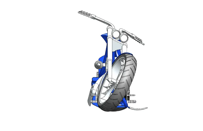
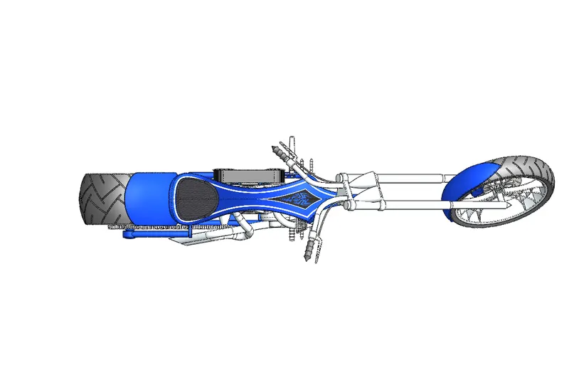
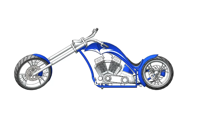
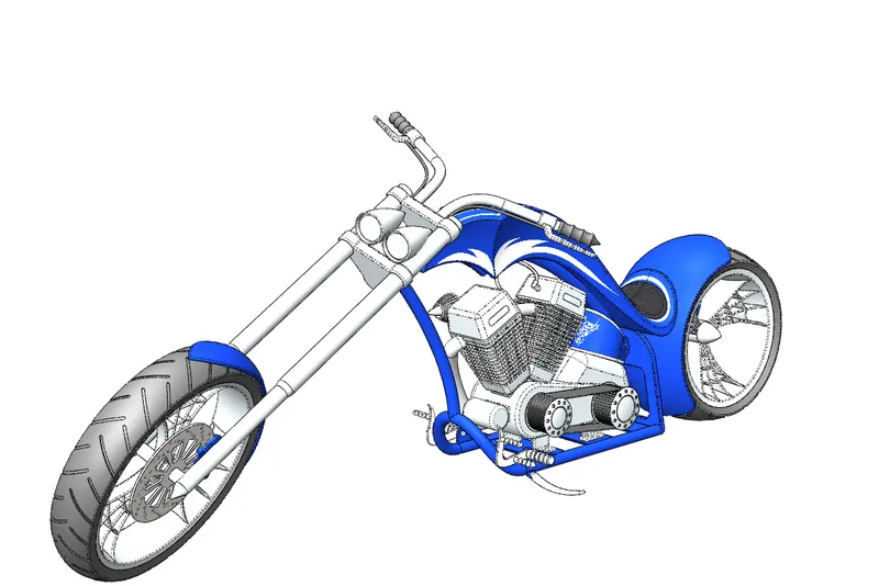
Addition of Decals, Camera set up, Lights, Environment & Photo view-360.
Decals:
Inserting images into parts outer surface is called as Decals. The decals are added for better and aesthetic viewing of a component.
Camera setup:
Cameras are used to adjusting and viewing at certain angle with some focal effects. In chopper assembly camera is faced over the isometric setup for better look.
Lights:
For front head lights and indicators these option is very useful at the time of rendering.
Environment:
Choosing the exact background effects for better viewing and assembly look at the time of presentation these option is very helpful. After the environment setup was done it is inserted in rendering option for better look creation.
Rendering:
Insert the environment setup view into render option and add the quality and illumination effect for making the rendered image. Finally view the images with the help of photo view 360 and make the images at high quality and look.
Conclusion
These are the various steps and procedures are followed to done the designing and assembly of American chopper with the help of Photo view 360 option in Solidworks and Solidworks visualization tool.