Radar Mast & Final Assembly of Yacht
Design of Predator Yacht and its components with photorealistic rendering by using Solidworks
OBJECTIVE:
Main objective of the project is to design and assembly of Predator Yacht parts in Solidworks 2020 with exact photo realistic rendering using photovie-360. Renders can be done by using decals, cameras, lighting and environment setups.
INTRODUCTION:
The project is about to achieve a Yacht assembly with the help of Yacht blueprint images by using non-parametric method of approach. The structure is about 33 metre long and it consists of 9 components.
In this Yacht assembly first and main process is to create a BLUEPRINT setup with the help of blueprint images. Insert the images in the corresponding plane and make sure that all the orientations are fixed properly. Finally create a new plane called MIDDLE plane and BACK plane too.
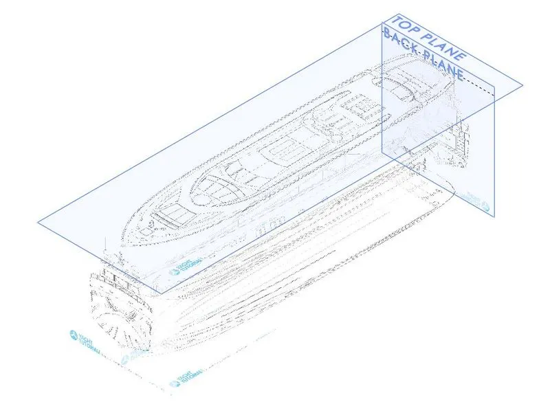
Blueprint Setup
DESIGN METHODOLOGY:
Overall design process is showed in a below flowchart.
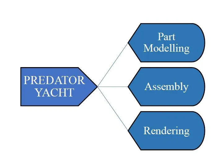
Design Methodlogy
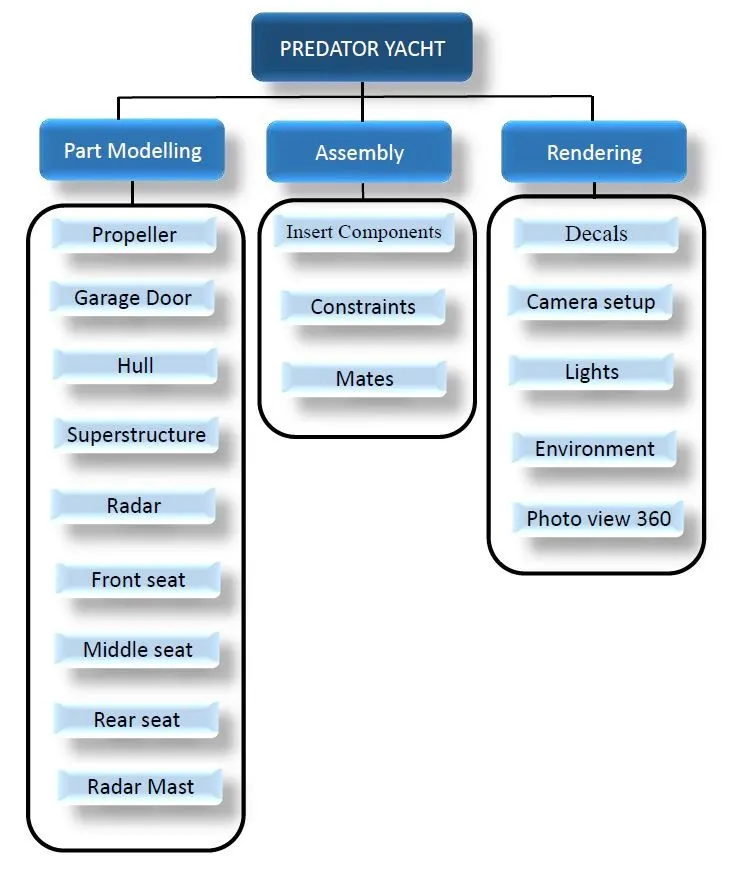
Flow Chart of Predator Yacht
DESCRIPTION:
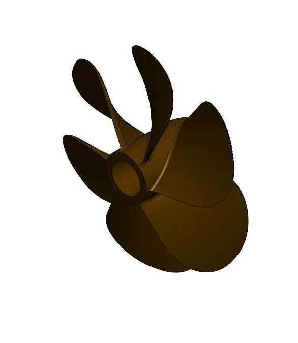
- PROPELLER
The component is used to provide a method of propulsion so the Yacht is able to move forward through the water
APPEARANCE:
Painted brown
STEPS INVOLVED:
Propeller was created by using Solid modelling process. For propeller start with centre area by using revolve option. Create a plane with respect to top plane and form a rectangular structure sketch and in the centre hub make the sketch with almost perpendicular to both of the sketch. Now use the loft option to create the fin with exact curve structure. Now make the fillet at the edge of the fin and use the pattern to make 3 fins equally spaced. Now give the colour code for full solid body with brown shade.
- THE HULL
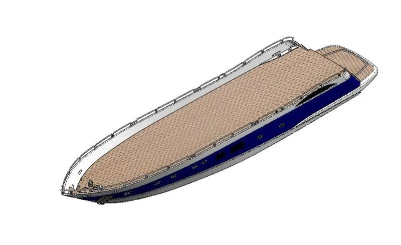
The hull is a watertight body of a Yacht. Normally hull is the main body to hang an overall weight and structure of the yacht.
APPEARANCE:
Painted Blue, White and main floor decals setup.
STEPS INVOLVED
Normally hull is symmetric in structure so half of the unit is enough to create a total structure. The hull is divided into 3 types of design structure while formation. 1. The base structure 2. Railings, aesthetic glass look 3. Decals for floor and painted outlook.
The first step is to insert the Blueprint setup and by using mid plane make projected cure option form the base structure of the hull with surface modelling concept. By using surface loft and surface sweep option the hull half structure was developed. The features like surface extend, surface trim, extruded surface, etc… are used for making the structure. After completion of structure b using knit option zip the every features into combine form with the deviation of 0.1mm maximum clearance. By using create solid option form the hull structure into solid form.
The railings at the top of the hull structure is developed by sweep option with the help of circle and guide line option. Repeated the same procedure for certain distance and formed a railings with the help of sketches.
After the half structure is created using mid plane option mirror the half structure into full form with merge entities option. Now use the colour codes for face option to fill the needed colour for each surface. After the colour code by using the decals option fill the area with wood type images to make the structure into extra look.
- GARAGE DOOR
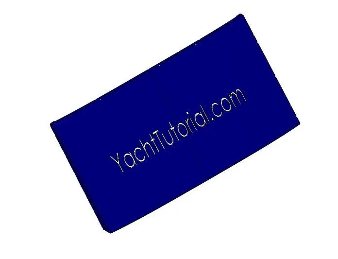
Door structure used to prevent the storage area in the Yacht.
APPEARANCE:
Colour painted.
STEPS INVOLVED:
By using the cut separate block form the main model the door is created. Extruded cut and fillets are the options are used to form the structure. The door has a projected text with the help of text wrap option done by using constructed line setup.
- FRONT SEAT
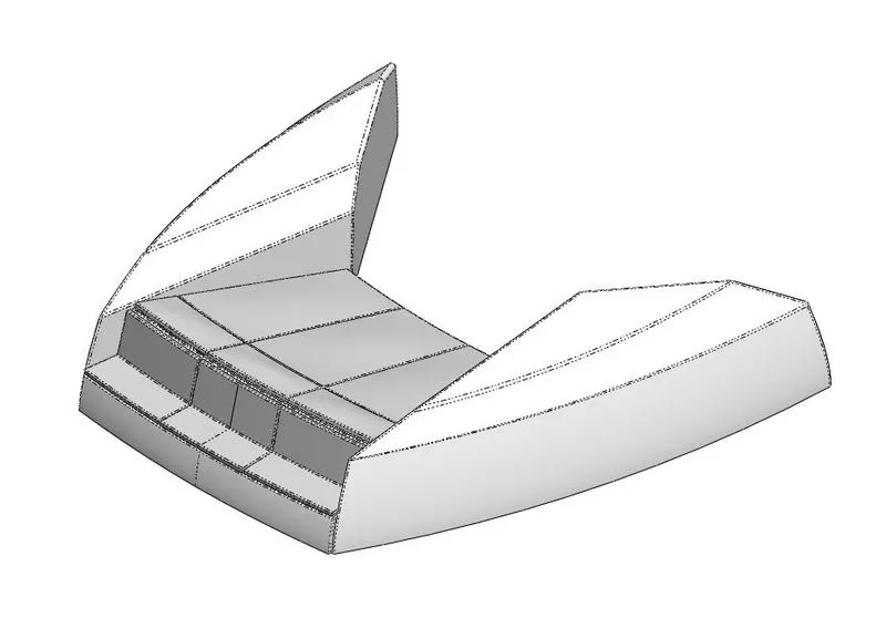
The yacht front area was covered by using this front seat. Its looks like a fin structure.
APPEARANCE:
Painted colour
STEPS INVOLVED:
Insert the blueprint setup and draw the splines with the help of top setup view as per in the blueprint. Now make sure that the structure and the splines has proper dimensions and finally go for the surface sweep option. By using surface extrude option make the half structure. Finally knit the half structure into single feature with 0.1 mm tolerance value. Now make the surface into solid conversion and add the fillets and chambers where ever needed. Finally make the mirror option to make the second half of the seat structure. Now use the colour code for the seat as dark grey and for outer fin structure as white.
- MIDDLE SEAT
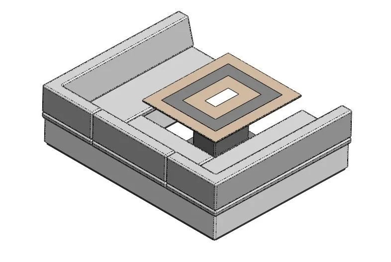
The seat is located at the middle of the yacht with table like centre structure.
APPEARANCE:
Painted colour.
STEPS INVOLVED:
Insert the hull surface and the blue print setup. With the help of top blueprint view draw the structure and make the solid orientation. Make sure the fillets and chamfers where ever needed. Fill the colour structure with the surface of seat as dark grey and base structure as white. Centre table also give the colour with the surface match as grey and brown.
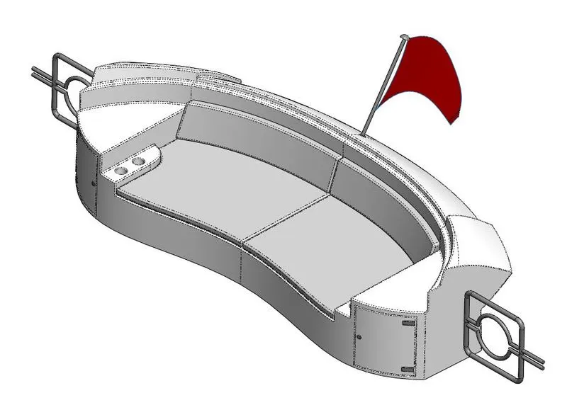
- REAR SEAT
The rear area occupying structure. Looks like a hull rear end with flag.
APPEARANCE:
Painted colour
STEPS INVOLVED:
By using the hull surface structure as base draw the outline of the structure with the help of top blueprint setup. Draw the splines at the end of the seat and by using surface sweep form a structure. Finally draw the curve grill type structure and make into solid. Now by using mirror option make the second half of the structure with merge entities. Now form a sweep at the rear end top as a needle and form the flag structure by using surface loft. Finally add the appearance painted area individually at each surface.
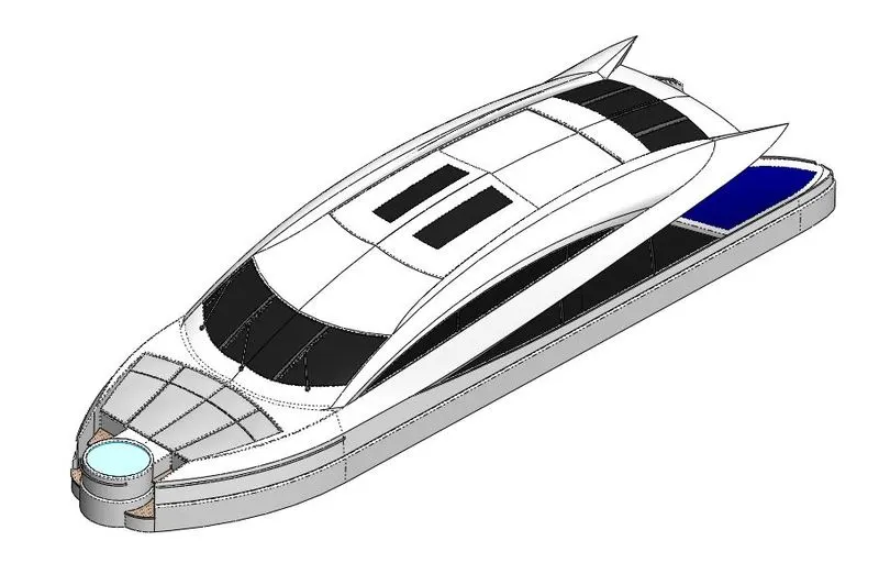
- SUPERSTRUCTURE
The main structure of the yacht. It is located at the centre of yacht with the total control of yacht unit. It looks like a home type structure with roof.
APPEARANCE:
Painted colour
STEPS INVOLVED:
Super structure consists of critical spline like looks so we go for surface concept and finally convert into solid form with only first half structure.
Insert the hull structure surface model and blueprint setup too. Now with the help of front and top blueprint views achieve the structures using splines and lines with respective planes. Finally go for the surface sweep and surface loft option for the front view faced structure.
Tools used for achieving the structure are surface loft, surface sweep, extend surface, trim surface, knit, filets, etc…
At last combine all the different structure into single form with the help of knit surface with maximum deviation of 0.1mm. And make the surface into solid conversion.
Now add the second half with the help of mirror option and remove the unwanted area at the top of superstructure with the help of extruded cut.
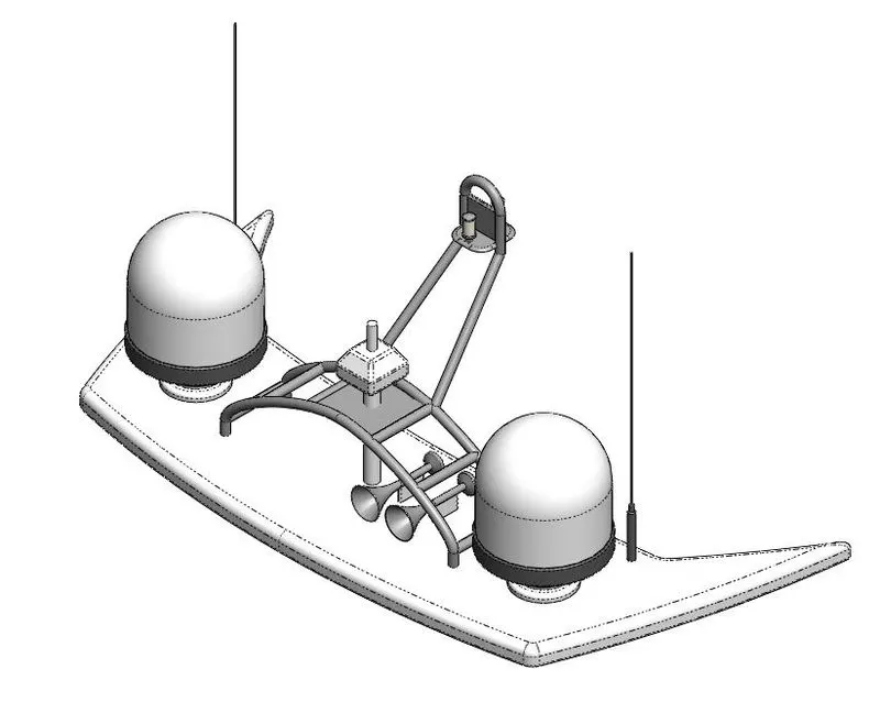
- RADAR MAST
Used to actuate the yacht at correct direction and acts as a communication device. Consists of antenna, signal receiver, etc…
APPEARANCE:
Painted colour.
STEPS INVOLVED:
Inset the blueprint and superstructure surface and form a new file called radar mast. With the help of surface draw the left side of the radar mast with splines and lines. With the help of loft option achieve the base structure. By using revolve option draw the radar signal box and antenna. Now make the horizontal revolve for making the horn with the help of shell option.
Now do the mirror option with the help of mid plane to form the next side of the radar mast and finally apply the appearance.
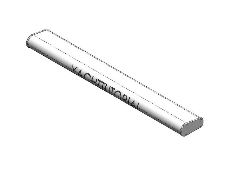
- RADAR
This device is used to receive the signal and used to identify the location in the coastal area.
APPEARANCE:
Painted colour
STEPS INVOLVED:
Draw two circles at some distance match to the blueprint setup and finished as closed sketch. Now make the solid extrude option to fill the structure and add some fillets and chamfers. Finally finish the object with appearance as white in colour.
ASSEMBLY AND RENDERING:
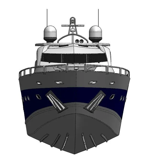
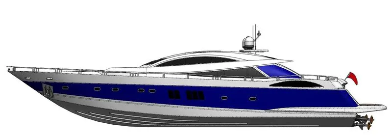
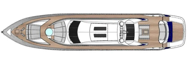
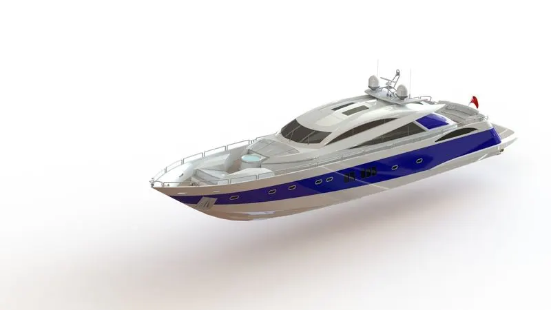
Mating of two components with proper constraints to make their application is called assembly and rendering is the aesthetic view of approach to a assembled model for presentation.
Steps involved in our YACHT assembly are,
- Insert the hull component in the assembly file location and make the component to assemble as default.
- Insert the superstructure and make the default option.
- Insert the radar mast and make the default option to assemble.
- Insert the front and middle seat separately and give the default option to assemble
- Now insert the rear seat and make the base face of the seat and top face of the hull in coincident, mid plane of both component also coincident and finally join the edge of the vertex into coincident.
- Insert the radar and add the concentric mate to join the radar and centre tube to join and using face top and inside face of radar and give coincident mate.
- Insert the propeller part and give the concentric mate for propeller and rear shaft, make coincident for propeller back and shaft front. Repeat the same steps for other two propeller on other two shafts.
RENDERING
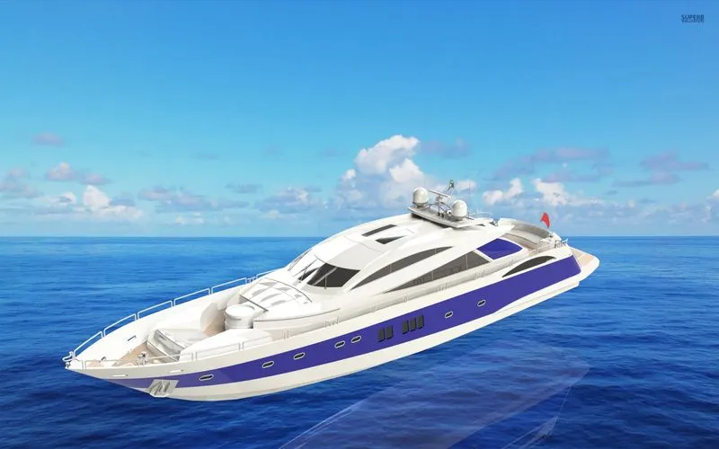
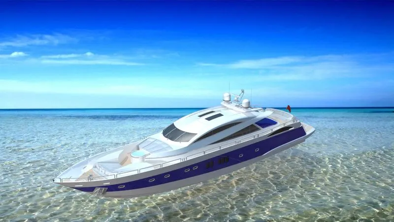
For rendering add the camera, lightings, decals setup are to be done. Now add the rendering image to the backside of the object and finally adjust the illumination and brightness values to make sure that the total rendering in a good viewing.
CONCLUSION
These are the various steps and procedures are followed to done the designing and assembly of Predator Yacht with the help of Photo view 360 option in Solidworks and Solidworks visualization tool.