Week 8 - Challenge 4 - Bumper
Week 8 - Challenge 4 - Bumper
AIM : To create the Bumper Design Plastic component through the given Class-A surface.
Objective
- To create a tooling direction.
- To perform draft analysis for given A-Surface and prepare the final close body.
- To design the Bumper plastic component by creating the B-Surface and C-Surface using the given Class-A surface.
- Take the Thickness of the component to be 3 mm.
Introduction :
The input of the product designer is in the form of the A-class surface. The job of the product designer is to create the B and C surfaces keeping all the aspects for the mold.
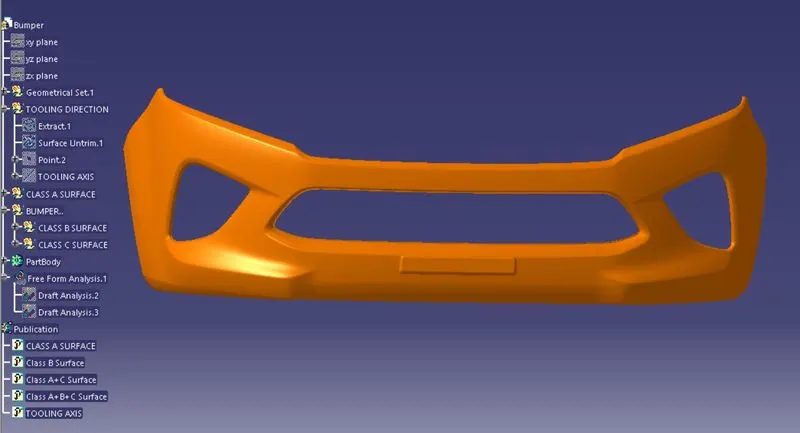
Class A Surface is
- Visible surface and aesthetic look.
- Surface with textures.
- Surfaces provided by customer(OEM).
- Don't have any features like(rib, snap, bosses, etc) on class A surface.
- Class A surface is made from scanned data with different software like alias etc.
- Surfaces which are having CURVATURE CONTINUITY IS CALLED class-A.
Class B surface is
- Invisible Surfaces.
- Surface mostly don't have textures.
- Surface needs to be created according to the class-A surface.
- Having all features(Rib,boss,snap etc) in B-side surface only.
- Surfaces which is having TANGENT CONTINUITY IS CALLED class-B.
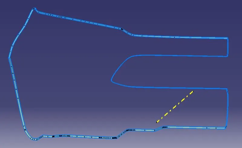
Class A Surface : Check the connectivity of the Class A Surface Ensure that there is no gap between the component, using join command. We can visually check it or by clicking boundary command. It has a boundaries outer. Therefore first check completed.
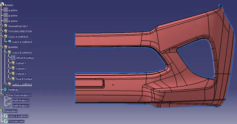
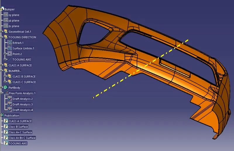
Tooling Direction for Plastic Part : Tooling direction is main consideration for plastic part and mold parts because it defines movement of mold part and possibility of plastic part to come-out from mold part (Core and Cavity).
- In Molding machine arrangement is given to open the mold along a direction which is known as Tooling Direction.
- In other words. The mold is built from two separate halves (Core and Cavity) and tooling direction basically define the direction of mold pulls apart.
- Tooling direction is known as primary direction.
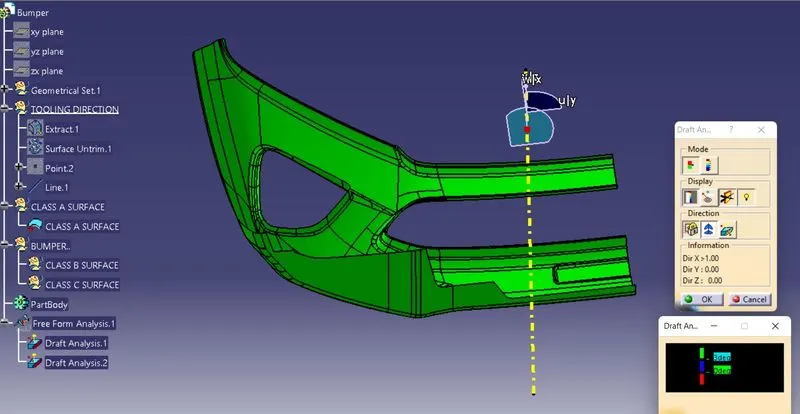
DRAFT ANALYSIS:
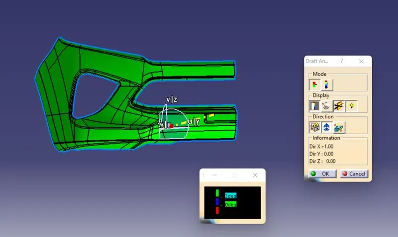
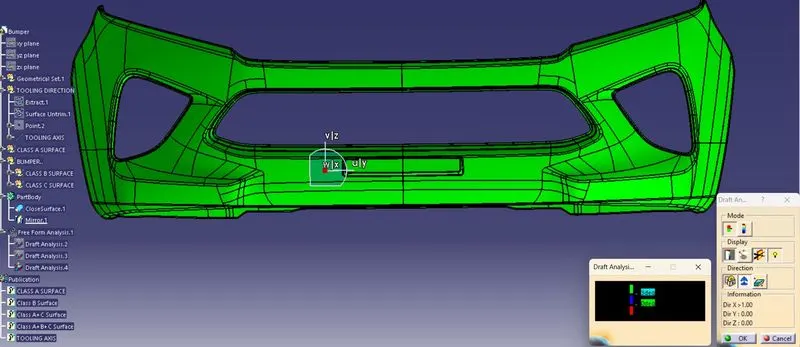
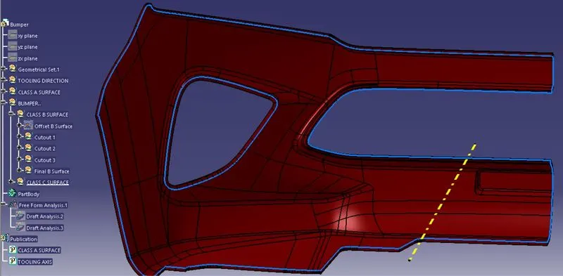
- The Drafting analysis was performed on the class-A surface by using the Feature Draft Analysis command.
- Using this command, the compass was set on the main tooling axis and the Draft angle was changed to 3 degrees.
CREATING CLASS-B SURFACE:
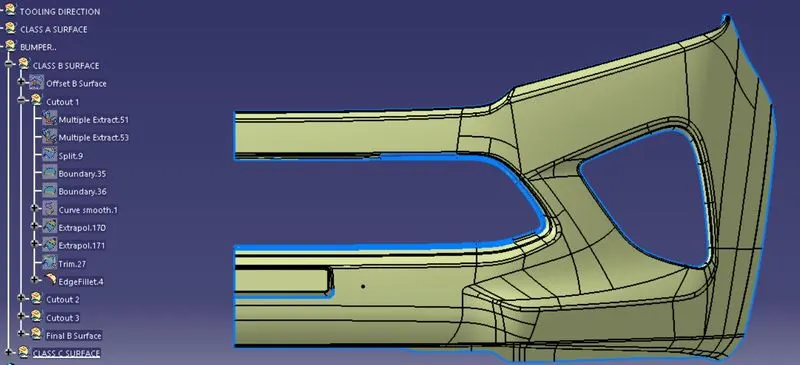
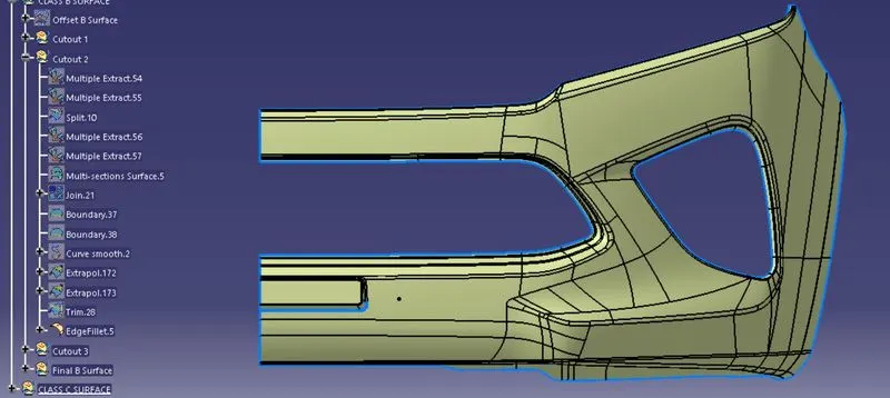
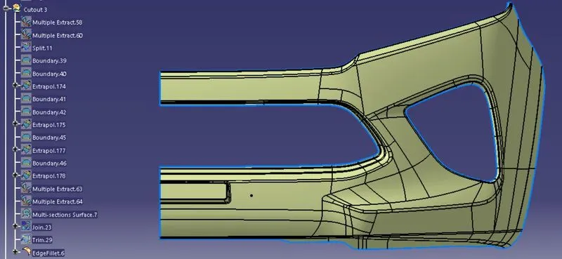
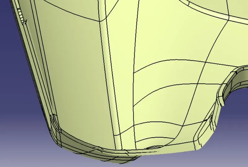
- To offset the class-A surface along 3mm for to create a B- SURFCAE.
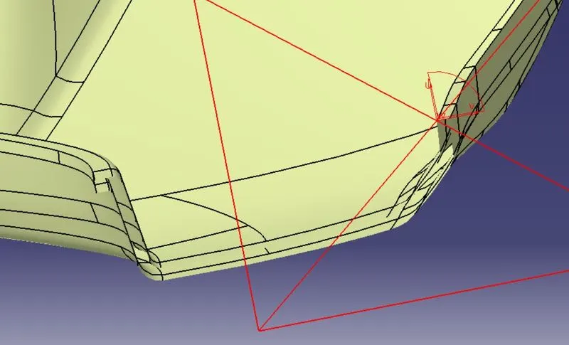
- Surface Gaps can be filled by using a fill tool and multi sectional tool.
CONCLUSION:
- To use class-A surface and create Tooling axis, Draft analysis were performed.
- The solid component was created from the surface model.
END OF REPORT........