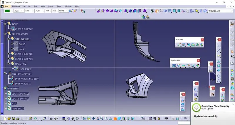
Week 8 - Challenge 4 - Bumper
Aim-
Create the Bumper Plastic component through the given Class-A surface. To begin with, the tooling axis for the given Class-A Surface should be created meeting the requirements of the draft angle and at the end perform the Draft analysis on the model.
Class A Surface-
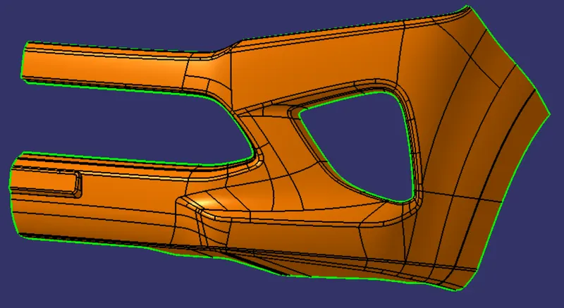
Class A Surface is the asthetic sutface that is created through scaning of clay model. This Class a Surface is a input CAD model for part design.
Class B surface-
Class B surface is created in a certain distance according to the thickness of the part. Class B Surface contain all engineering compoonent.
Class C Surface-
Class c Surface joins the Class A & Class B Surfaces.
Given Class A Surface-
Class B Surface Creation-
To create Class B Surface first Extract The class A surface using 'Multiple Extract' command. Then Offset The extracted surface with propere distance and direction(Downerd), where distenmce is nothing but the thickness value of the part. In this case some part of the surface might not be offseted. For those areas we have to use 'Multi-Section Surface' & 'blend' command with proper edge and guide curve and have to create those areas. Sometimes it might need to extract that perticular area of surface and then follow the same process to create the surfacxe.
Here I have offseted the class A surface and my reasult was-
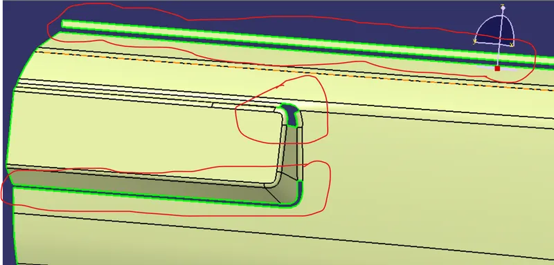
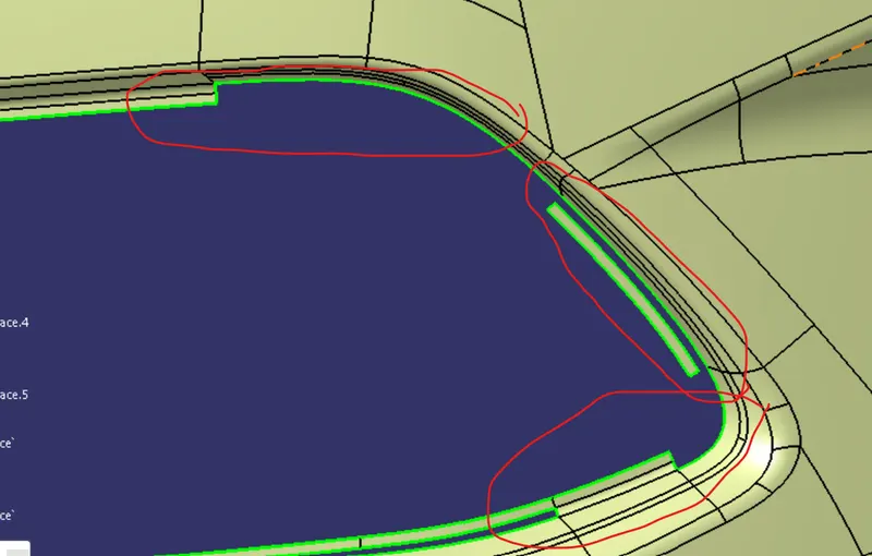
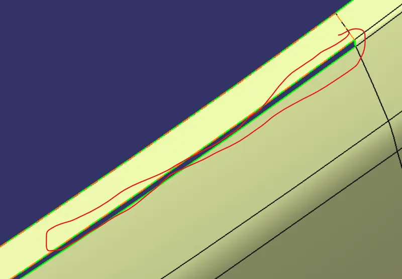
So in my case those perticular areas are not offseted properly. And I have created those surfaces following the process that i have explained above.
And my final Class B Surface was-
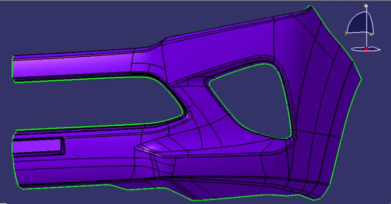
Class C Surface Creation-
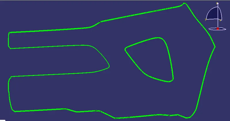
What Class C Surface does, is join the both Class A & Class B Surface. So to create the Class C Surface, first create boundaries using 'Boundary' command with using edges of Class A Surface. And then create a surface using 'Sweep' command at a angle of 90 deg. with class A Surface using those boundary. It might create error when try to make sweep with one single boundary of Class A Surface edge, so for that case we have to take several boundaries according to fisabilioty. And then trim those sweep surfaces with class B surface to make sure there is no excess surface beyond class B surface. So my final Class C Surface was-
Final Closed Surface-
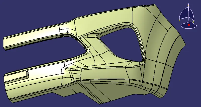
After creating all surfaces, join them togather using 'Join' command. And my reasult is-
Solid Body Creation-
To create solid body of that closed surface, make sute there is no open edges. If there is open edges then it would not be possible to create solid body. After make sure, go to part workbench and make the closed surface part a solid body using 'Closed Surface' command. this operation must be inside a 'Body' set not inside a 'Geometrical Set'. So my final solid body look like-
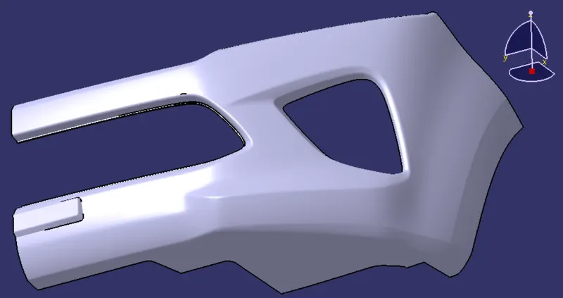
Draft Analysis-
Draft analysis is a most importent thing for a part body design. Its reasult says that the perticular body is manufacturable or not. Even it also analise that how simple or complex will be the manufacturing process. So to do that analysis first we have to create a tooling axis that will be along the movement of mould open and close axis.
Tooling axis-
For this case as head lamp hole is concerned, so we will consider the perpendicular axis of that head lamp hole for creating the tooling axis. So we will analyse bothe perpendicular plane of that head lamp hole.
Plane 1-
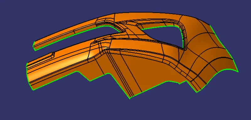
Draft Analysis of Class A Surface-
As we can see from above image that all the surfaces are clearing the draft angle.
Draft Analysis of Solid Body-
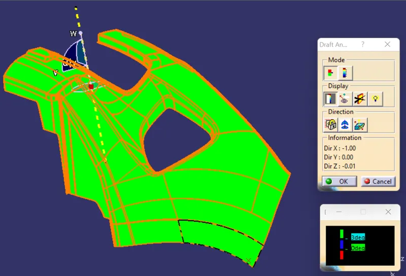
So from the picture we can say that all surfaces of solid body are clearing the minimum draft angle. From the reasult we can say trhat part is manufacturable.