Week 8 - Challenge 4 - Bumper
Aim
To Create Bumber and add thickness to it and generate the Draft Analysis on a sold surface.
Procedure
Check for any opening in the given Bumper model by using Boundary . In Boundary> select the edges or select the edges using Multiple extract.
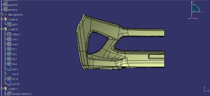
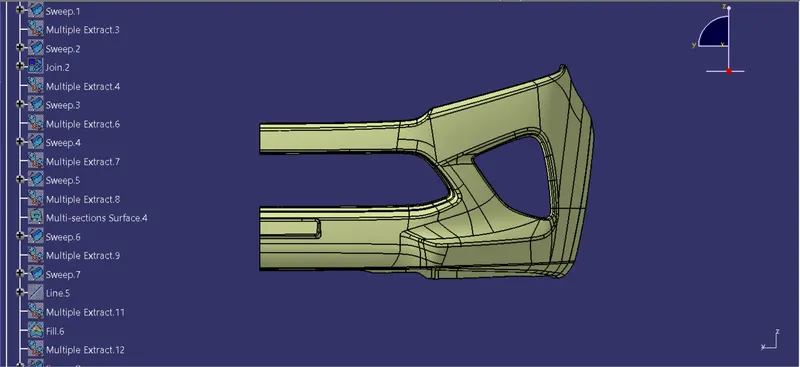
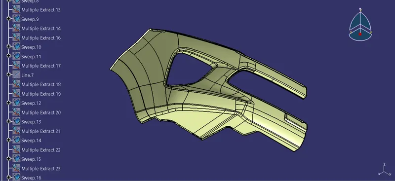
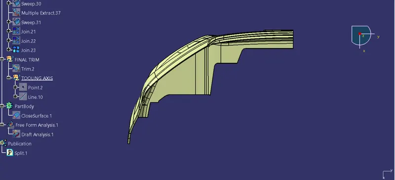
Creating Tooling Axis
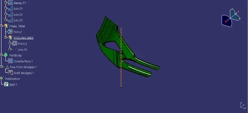
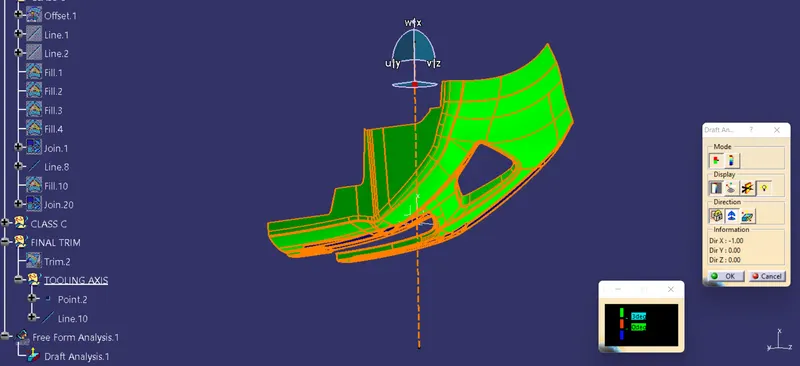
1. Create a point at the center of the base by using Point Definition by extracting the surface and selecting the surface
2. Create an axis system at the point that is created the surface using Axis system definition by selecting the point.
3. Now create an intersection in the ZY plane by intersection Definition for the Bumper.
4. Now using Point-Point in Point Defintion extend the line to take reference drafted lines on both sides and bisect those lines to get the direction in the ZY plane.
5. Create an intersextion in the ZX plane and a Tooling axis in the ZX plane
6. Bisect those two tooling axis lines and create a main tooling axis and name the bisected line as Main Tooling axis and do the draft analysis for the Class A surface.
Create B surface
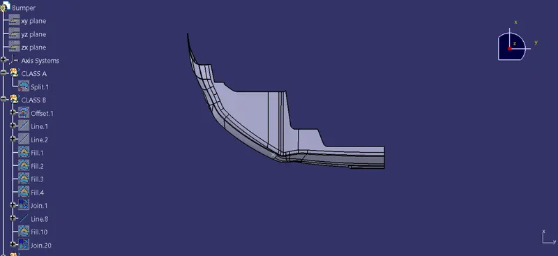
1. Now create the Plastic design for the Class A surface of the Bumper by creating the Class B and C surfaces.
2. Create a Geometric set in a tree and name it. Offset the class a surface to a certain distance as in it.
3. Cover the empty cavity formed during the offset by using Fill command.
Create C surface
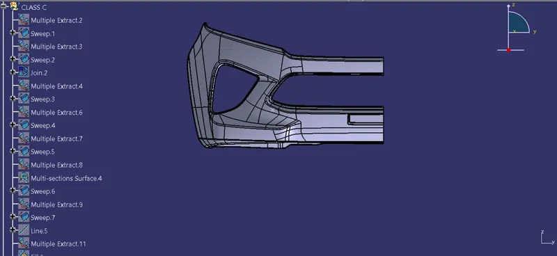
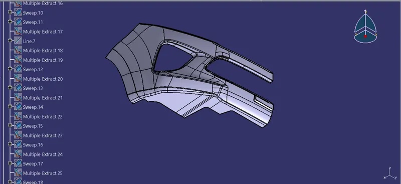
1. Create the Class C surface for Class A surface by using Multiple extract option by selecting the boundaries . Create a smooth curve for the extracet boundary. select the extraced boundary.
2. Extact the outer boundary wall and replace the Multiple extract with smooth curve.
3. Now using the sweep option create the C surface by selecting the Subtype with refetrence surface and Guide curve as - Boundary which is extraxted and Reference surface as - Extracted boundary surface and Angle of 90 - 93 degrees to maintain Draft Angle
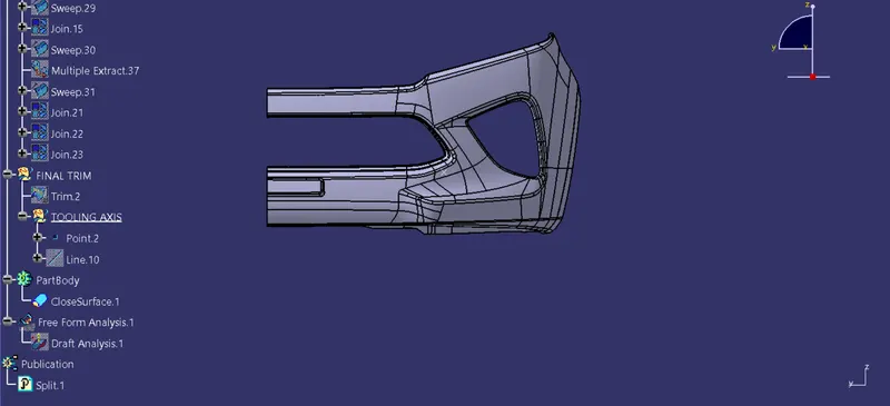
4. Check for open boundaries in plastic design and create the solid surface for the design in part design using a closed surface option.
5. Now do the draft analysis for the solid component tooling axis and check for the fraft angle as it should be in green in colour in the tooling axis.
Result
Created the Plastic design for and added thickness to it and generated the Draft Analysis on solid surface for Bumper.