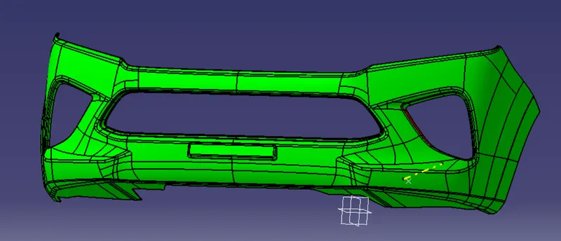
Week 8 - Challenge 4 - Bumper
Aim :
To create the Bumper plastic component through the given class A surface and create the required tooling axis and perform the Draft analysis on the model.
Objective :
- First create the required correct tooling axis and perform the Draft analysis on the class-A surface.
- Create the class-B surface and class-C surface by using the surface modeling tools.
- And make the closed surface of class-A, class-B and class-C as the single solid body.
- And perform the Draft analysis on the solid model.
Theory :
Tooling Axis :
Class-A surface is first analyzed to create the tooling axis or tooling direction that molds pull apart in injection molding. Tooling direction is important for plastic product design as it decides direction for mold separation.
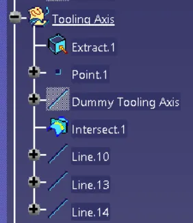
Steps followed for creation of tooling axis :
- Reference point is first created on the extracted surface.
- New axis system is deployed to plot clearance lines.
- The X-direction and Y-direction along the class-A were used to create tooling axis.
- Graphic properties of tooling axis were change before publishing.
Draft Analysis :
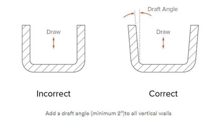
The Draft angle is the amount of taper for molded or cast parts perpendicular to the parting line. It can be measured in degrees. A functional part for injection molding has to have drafts facing both cavity and core sides to reduce the risk of damage to the parts and ensure ejection. And also important is to overcome the vaccume forces by letting air in between the metal and plastic for the part to release properly. Adding maintaining a decent cosmetic finish.
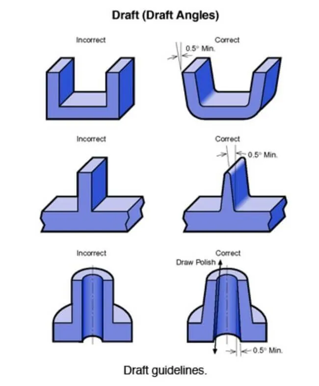
Draft should be a part of design for manufacturing and plastic product Designer should be aware of its need at the outset of the Design process. This allows considerations for design requirement to be taken into account.
Nominal values for Draft angle :
- 3 Degrees is the nominal Draft angle.
- 7 Degrees for textured surface.
- At the minimum of 0.5 Degrees can be manufactured by special tools. But it will increase the manufacturing cost.
Tooling Axis Creation :
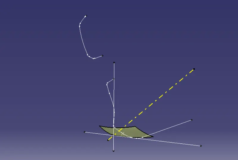
First step is observe the given class-A surface deeply and we can say the hole present area will be perpendicular to the tooling axis. so we first create point on the surface which is near to the head light hole as shown in figure.
CREATION OF THE TOOLING AXIS
TOOLING AXIS
It is nothing but the direction in which the mold opens and closes the draft angle needed to be provided by considering this tooling axis.
We can create a tooling axis by using the bisecting method.
BISECTING METHOD
This method is used for the generation of the tooling axis for that purpose first we need to decide the direction of molding and then we create one dummy tooling axis for the reference to the purpose.
In this method, we select the surfaces which can create problems and take intersections with respective planes in the x and y-direction. By using these intersection curves we draw two lines and then draw a bisecting line from these two lines in the x-direction and y-direction.
After completing this we need to draw a final line bisecting these two tooling axis in the X and Y directions to get our final output.
DRAFT ANALYSIS FOR THE CLASS-A SURFACE -

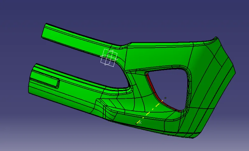
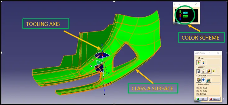
In the above images, the draft analysis of the Class A surface has shown the draft angle should be more than 3 degrees and this can be clearly observed from the above images that the surfaces have an angle of more than 3 degrees.
Class B Surface Creation -
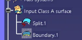
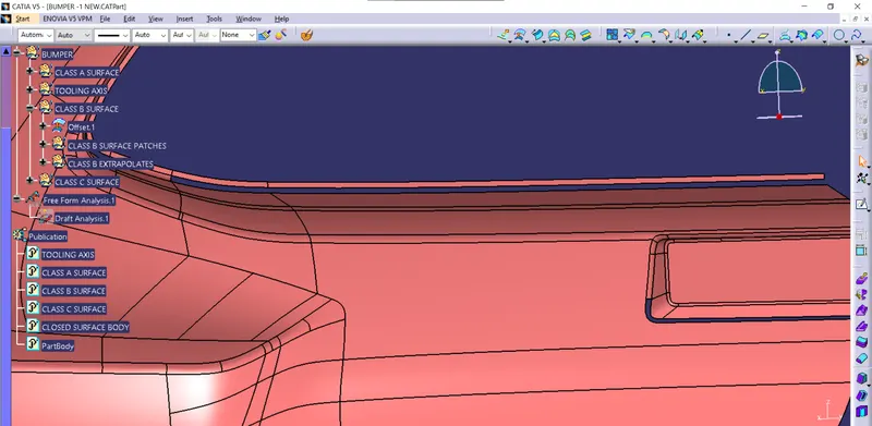
Tree diagram Steps Followed to create class B Surface -
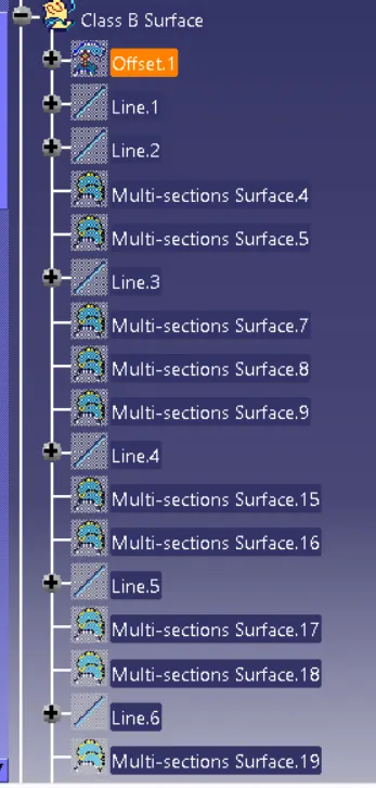
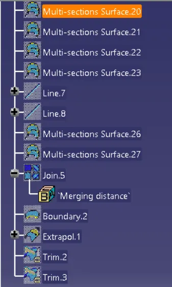
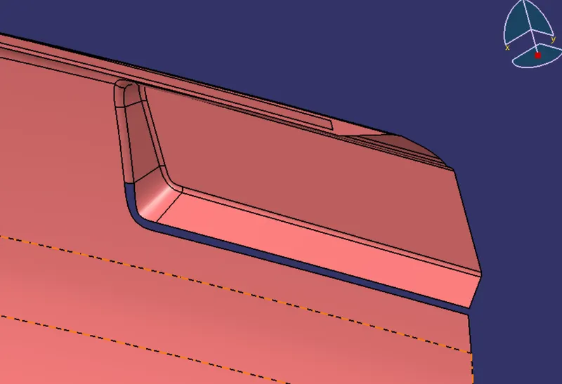
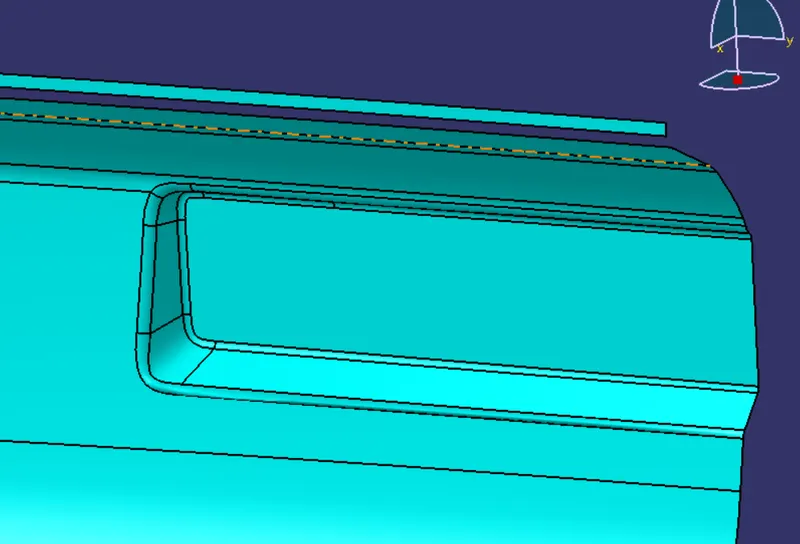
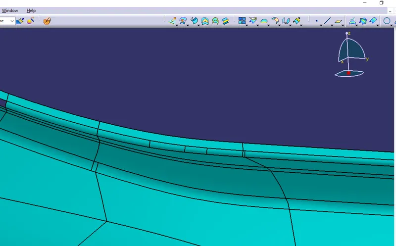
To create the class B surface, offset the class A surface inside as per our thickness requirement (here the thickness is 3mm, so I offset the class A to 3mm inside). Once the offset is created, we can observe some patches on the offset surface by taking the boundary for the offset surface, those patches are formed due to the fillets on the class A surface. We need to cover those patches with the help of the multi-section surfaces command by extracting the patch boundaries. Once all the patches on the offset are covered properly join all the patches with the offset surface, to get the replicated surface of the class A surface.
Patch-1:
Patch-2:
Patch-3:
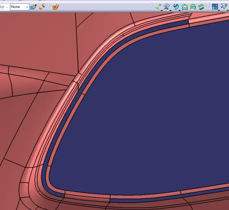

Patch-4:
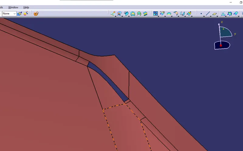
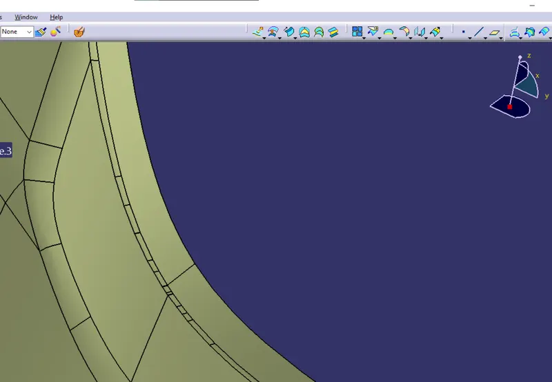
Creating Class C surface -
Tree diagram image -
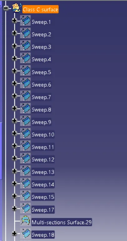
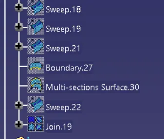
C suface Image-
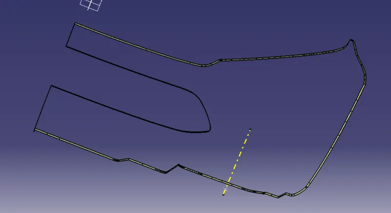
Now By using Join Command Join A And C suface First and then trim B surface from this joint to create a surface body .

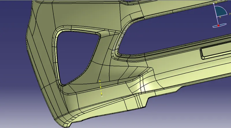
Now By using close surface command created a solid surface having thickness 3 mm .
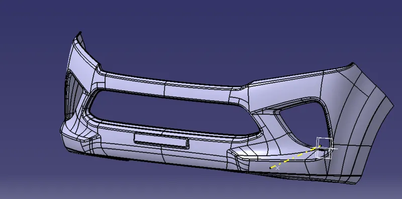
Draft Analysis for solid body -