Week 8 - Challenge 4 - Bumper
BUMPER DESIGN
AIM
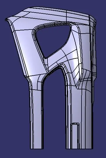
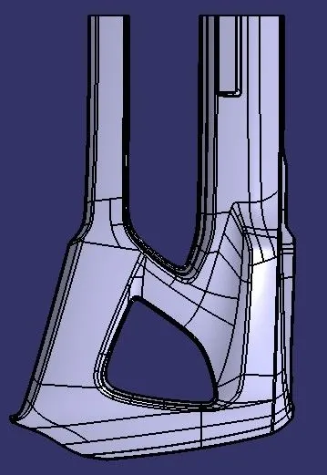
This Report aim is to perform draft analysis for the given surface by defining a tooling direction appropriate to the shape of the surface and also to create the class-B,class-C surfaces and final closed body with the help of given Bumper Class A surface.
THEORY
Class A surface:
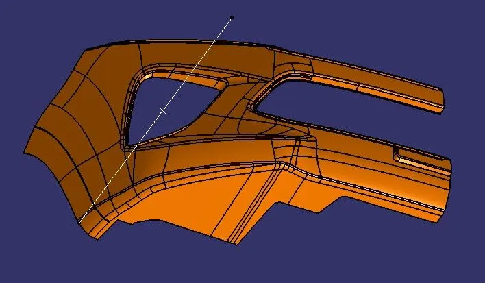
This is the styling surface which provides the aesthetic features of a component. A designer starts the design of component from a class A surface.
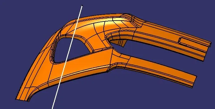
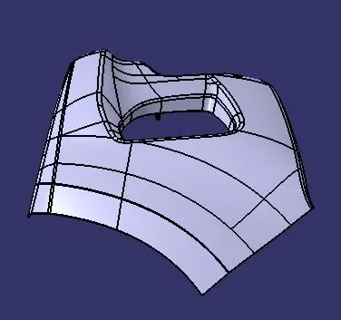
Given class A surface
Class B surface:
Class B surface is obtained by offsetting the class A surface by the component thickness value. This B surface contains all the engineering features of the component. So it is also called as Engineering Surface.
Class C surface:
Class C surface is created along the tooling direction of the component and it connects the class A and class B surfaces.
Tooling Axis:
Tooling axis is the direction in which the part is released from the mould.
PROCEDURE
1. Check for discontinuity:
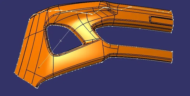
The first step any design engineer must ensure is the continuity of the surface received. In CATIA this can be verified by two operations: join,boundary.In some cases, this can also be approved visually. Appropriate steps are to be taken if the surface has any discontinuities.
2.Defining the tooling axis:
Tooling axis is important for manufacturing any plastic component. It is the direction in which the plastic part is drawn after the completion of molding. So, it is important to have a good tooling direction.Generally direction normal to the flat surfaces/ holes in the component design is considered as the best tooling since it makes the whole operation easier and there by cost effective.

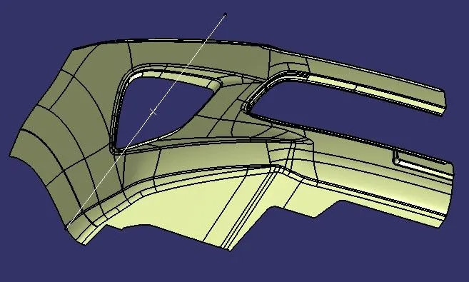
 3. Creation of B surface
B surface is created by offsetting the class A surface by 2.5mm and if there are any surfacesnot offsetted then they will be created by using multisection surface or sweep command.
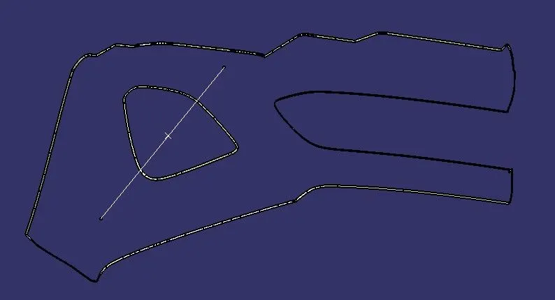
4.Creation of C surface
C surface is created by using boundary of A surface. with the help of sweep command surface is generated perpendicular to the edges of A surface.
Final closed body
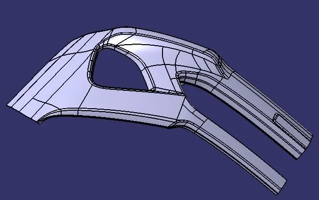
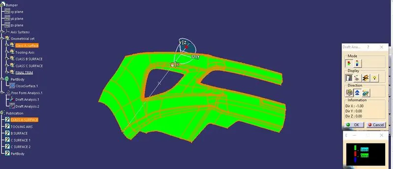
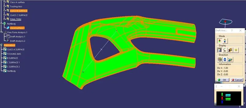
Draft Analysis:
Draft analysis is an operation that is performed to know the draft angles of the surfaces concerning the tooling direction. The minimum feasible draft angle for this design is taken as 3 degrees. Generally for plastic components, a minimum draft angle that can be achieved is 0.5 degrees.
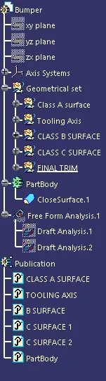
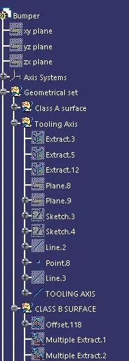
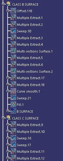
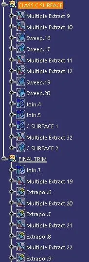
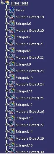
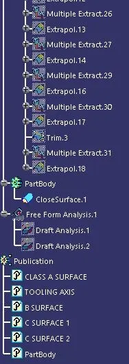
Detailed Tree structure
Different views of Final Closed Body
Isometric view
Front view
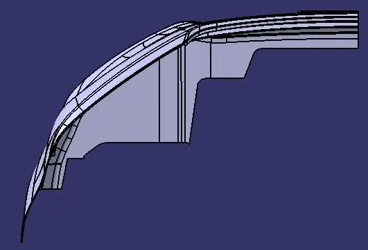
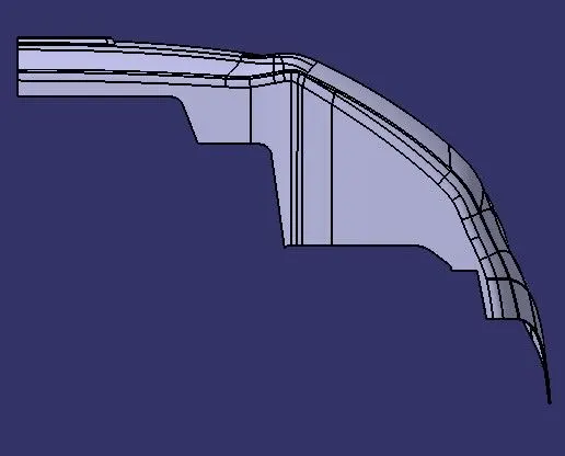
Side view
Top and bottom views