Week 8 - Challenge 5 - Core & Cavity Design
AIM :
To create CORE AND CAVITY from the previews switch bezel exercise.
Tooling axis
When a machine with one or two rotary axes on the head is referenced by the Part Operation, you can check machine accessibility when defining the tool axis of a machining operation. The Tool Axis dialog box includes more options in this case.
STEP 1:
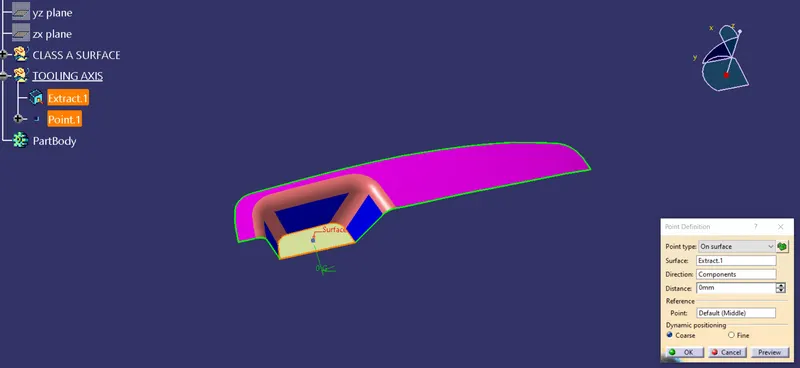
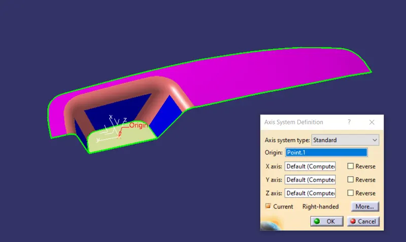
create a point in the center of the given switch bezel surface and place an axis system on the point.
STEP 2 :
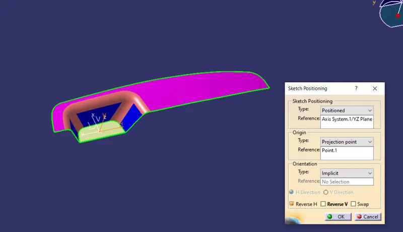
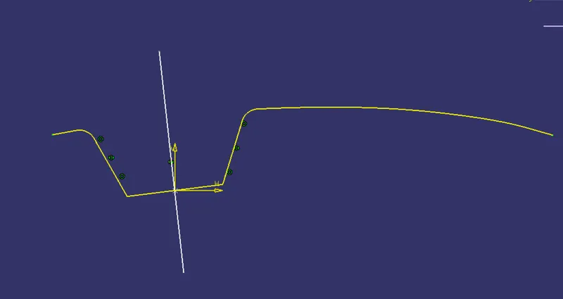
Insert a positioned sketch in the YZ plane and project 3d element of the class A surface. after that create two lines on the inclined lines of sketch, bisect both lines with line command.
STEP 3 :
Insert a positioned sketch in the XZ plane and project 3d element of the class A surface. after that create a line on the inclined lines of sketch, bisect both lines with line command.
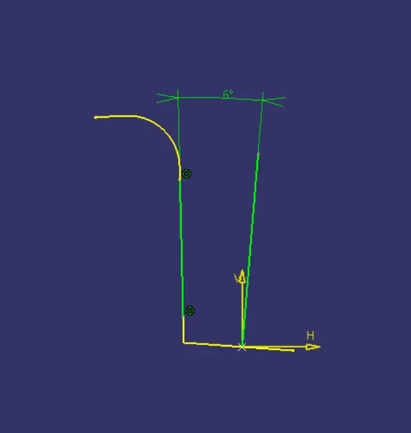
STEP 4 :
bisect both lines obtained from sketch 1 and 2, the obtained line is TOOLING AXIS.
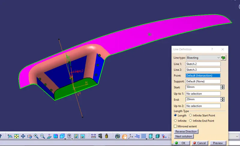
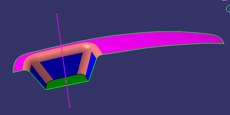
After tooling axis crate class B with the reference of class A surface.
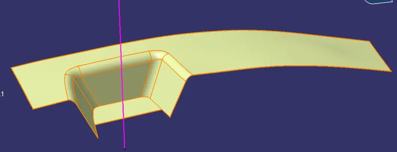
now create C surface and join the C surface with A surface and trim it with B surface.
now the closed surface command from the part body to form a solid.
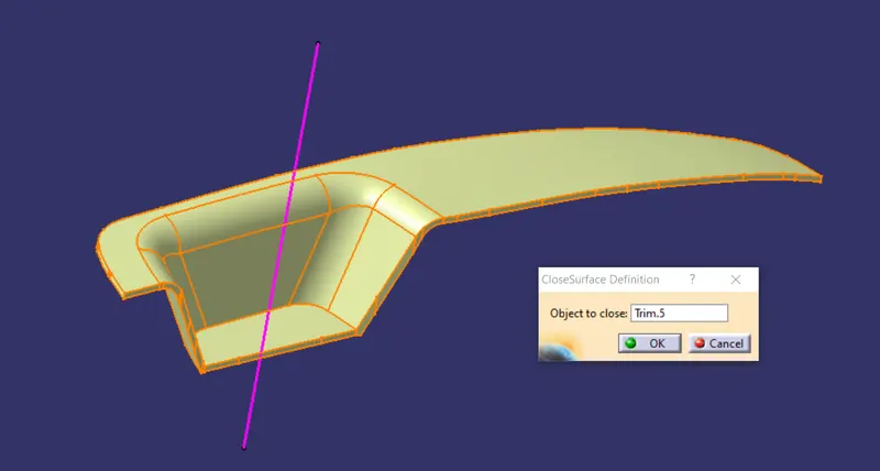
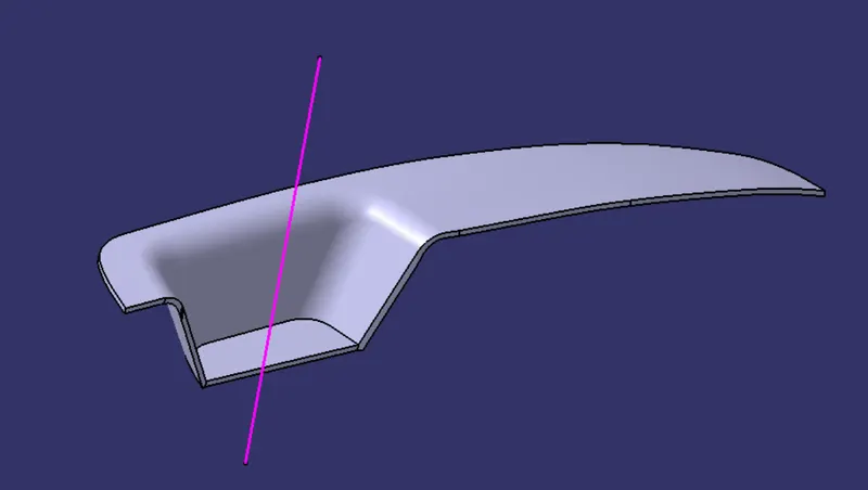
DRAFTING
It is a tool that allows the user to ‘see’ whether the part they are designing can be removed from the tool being used to make it. In the case of plastic injection molded parts it also allows the designer to see if there is enough draft on the part to ensure that it can be correctly grained. I always use the tool with the axis direction method. Put the main axis on the draft direction line with Z being parallel to it. Select the tool then select the part body. You may need to reposition the axis again. The results window has 2 options 1 with just 3 color variants and the other with many variants. They can be edited by double-clicking on them to give you the result you desire. The colors show the different draft angles
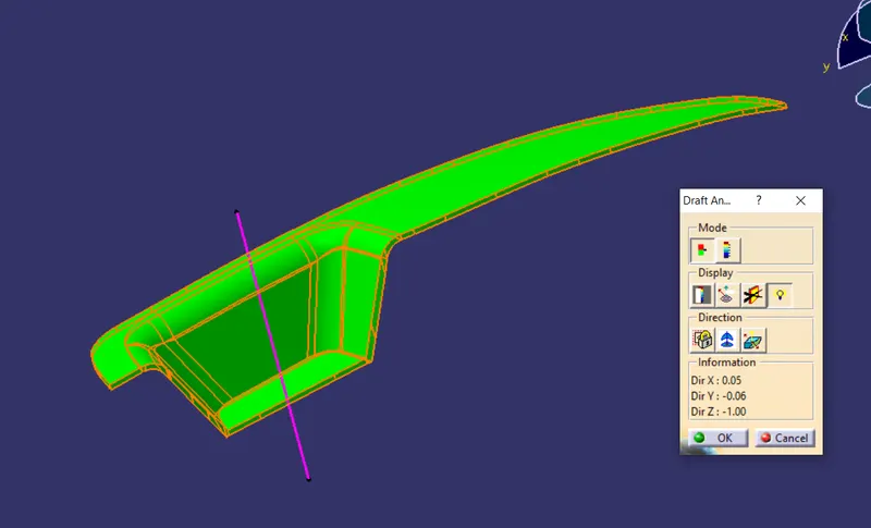
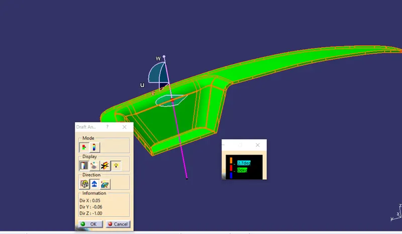
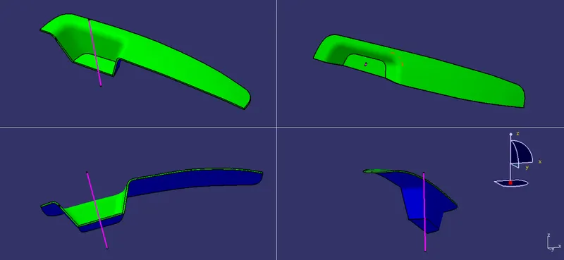
CORE AND CAVITY
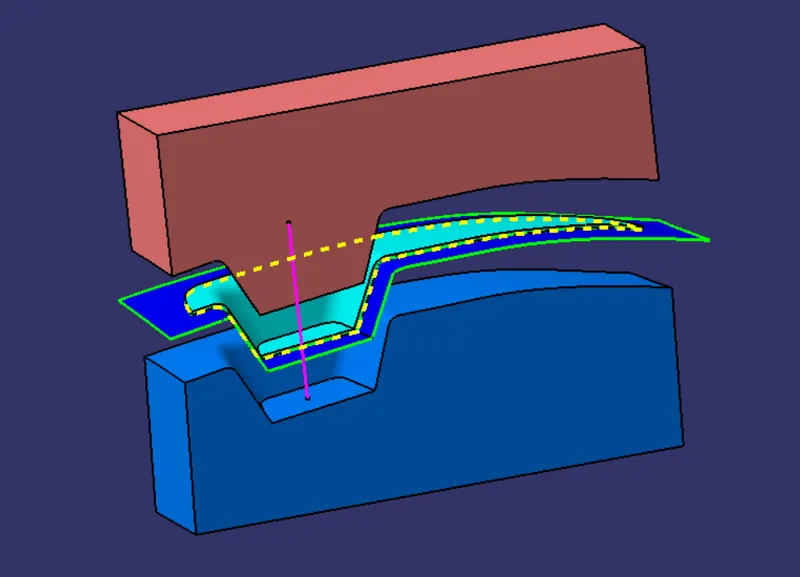
The core & cavity are the shaped sections in either half of the mould tool which give the plastic product its final shape. The hot molten material is injected into the core & cavity and then sets hard into shape. The design of the core & cavity is essential in the correct formation of the product.
PARTING SURFACE
Create a boundary of class A surface.
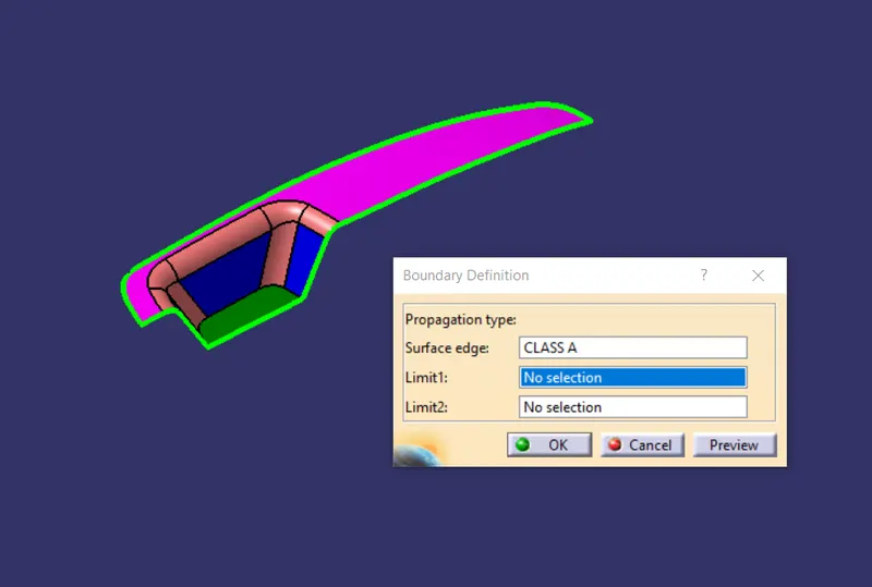
Extrapolate the boundary
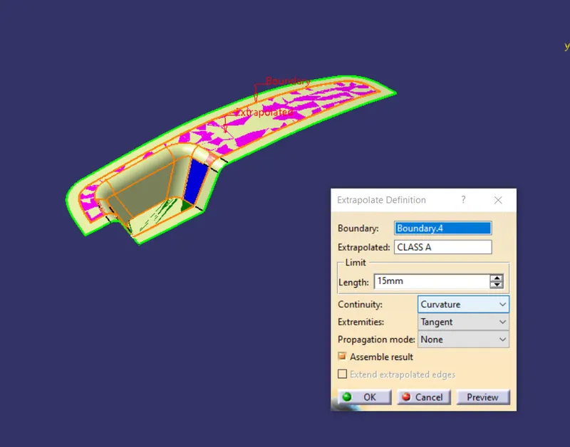
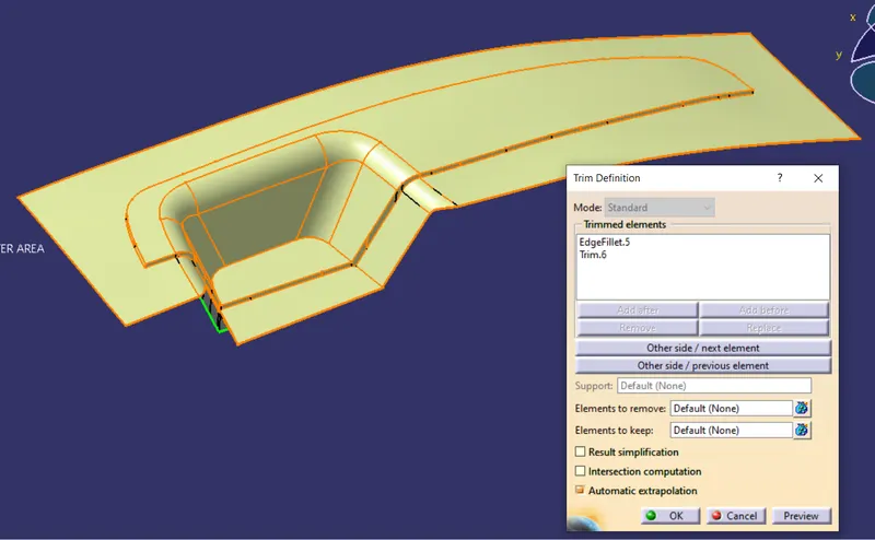
trim the extrapolate surface with class C .
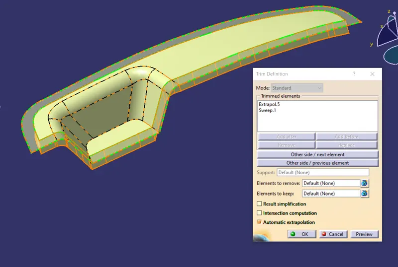
now trim it will class B surface , parting surface will obtain as shown in fig
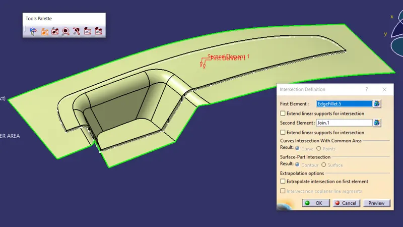
create a intersecting between the parting surface and class B , the boundary occur is known as parting line

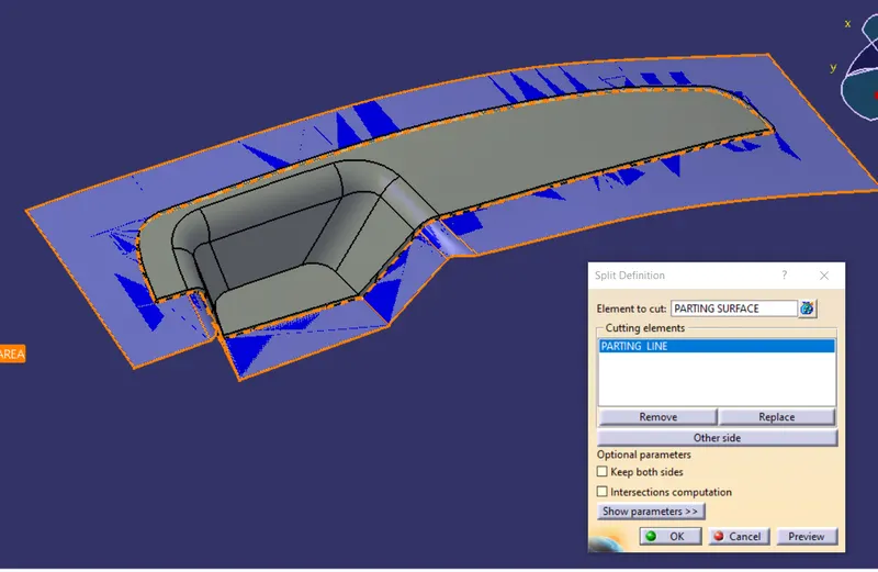
split the parting line with inner parting surface
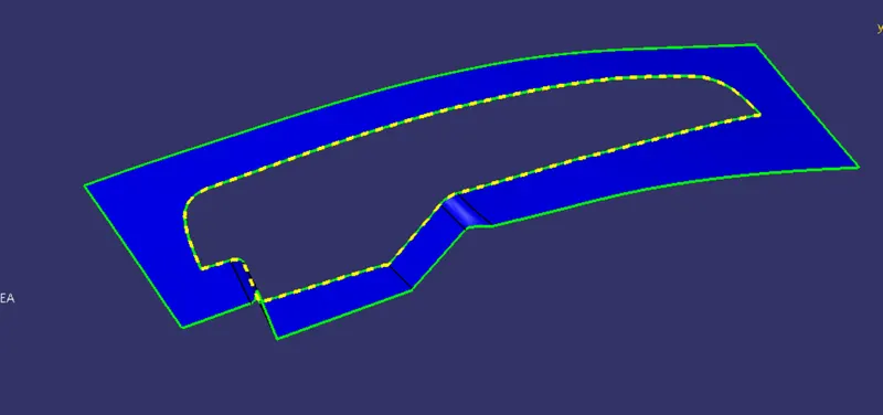
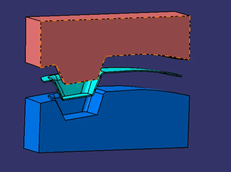
CORE
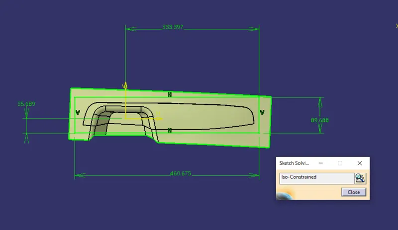
create a sketch and draw rectangle on the xy plane
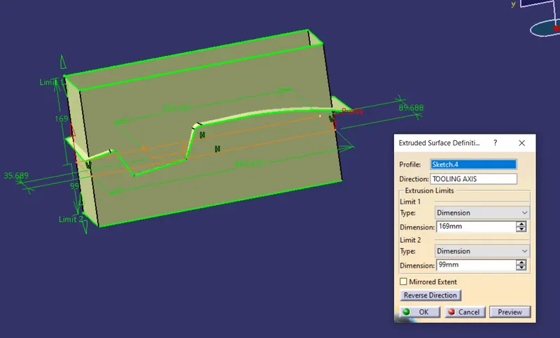
extrude the sketch with reference of tooling axis direction
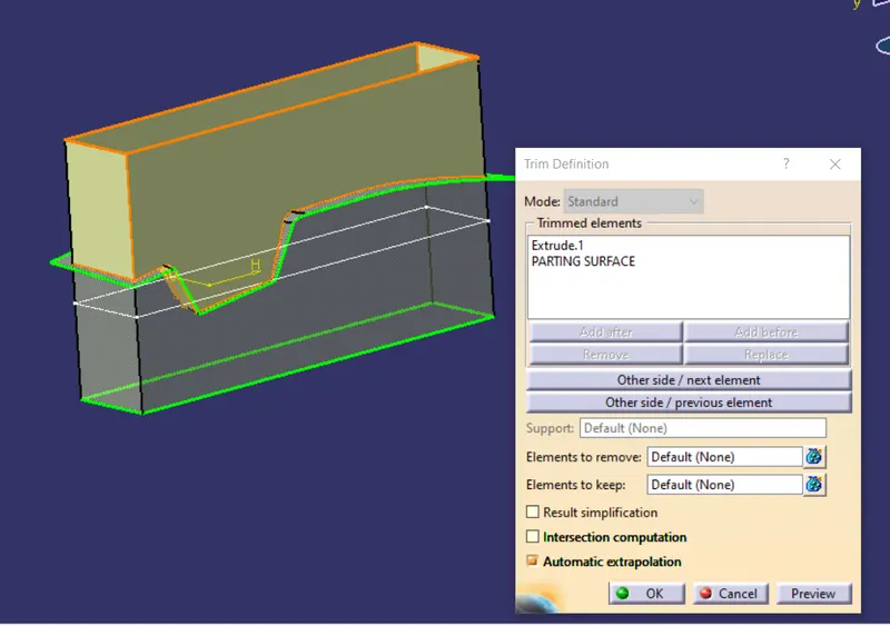
trim it with paring surface
create a boundary and fill it.
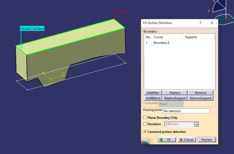
join the fill and the trim
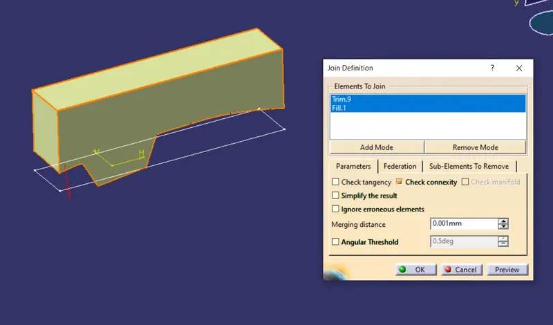
CORE
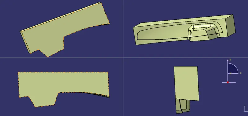
CAVITY
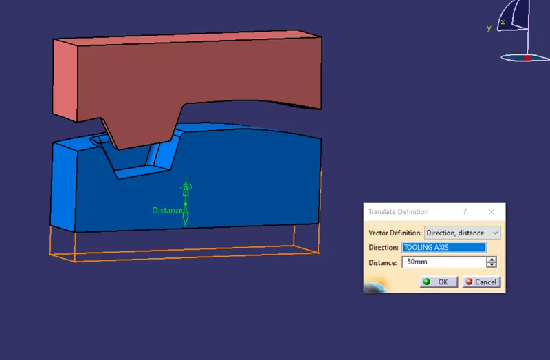
Extrude the same sketch with tooling axis direction
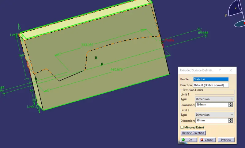
trim it with b surface
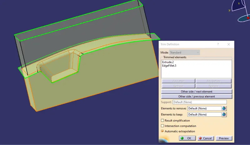
cavity
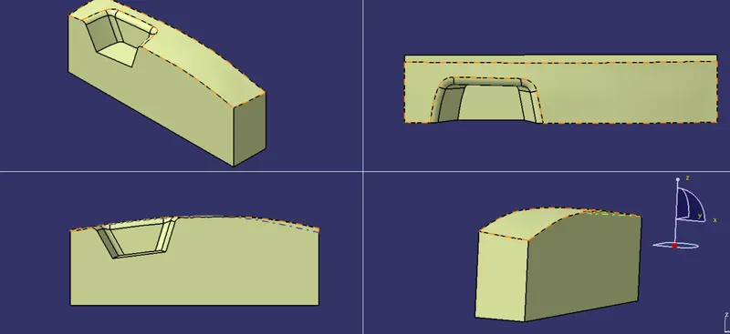
CORE BLOCK
now in part design , make the core surface as solid by using closed surface .
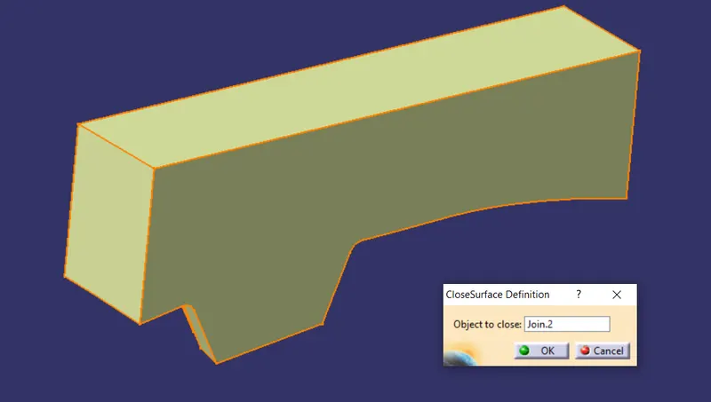
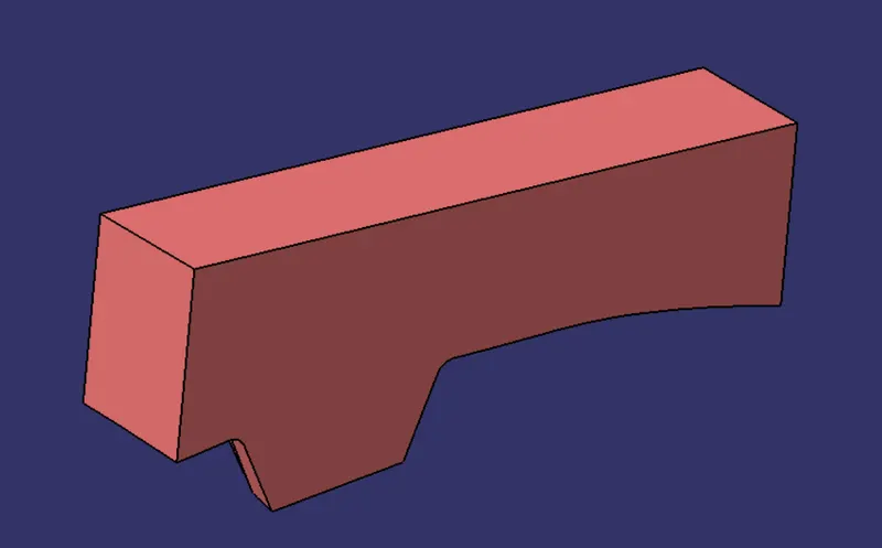
CAVITY BLOCK
now in part design , make the core surface as solid by using closed surface .

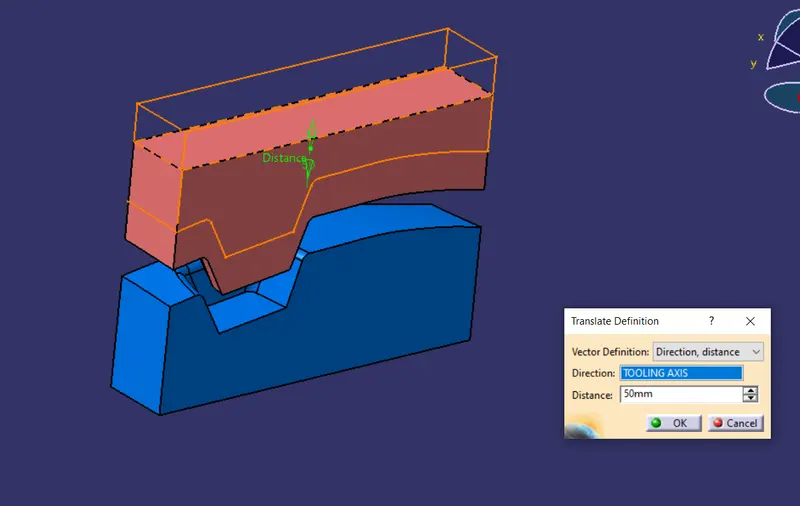
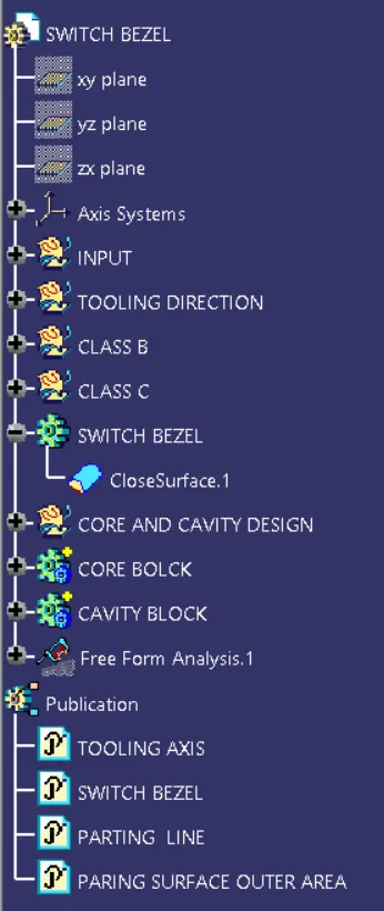
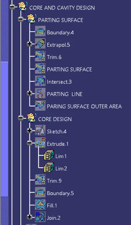
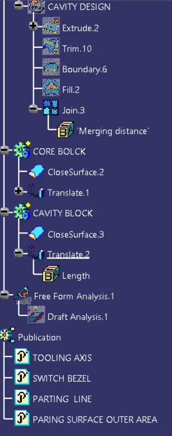
TREE STRUCTURE