Switch Bezel Design
Aim - Create the Switch Bezel Plastic component through the given Class-A surface. To begin with, the tooling axis for the given Class-A Surface should be created meeting the requirements of the draft angle and at the end perform the Draft analysis on the model.
Procedure -
- before starting to work on the part we have ti see the connectivity of class A (the give input is closed or not )(use join).
- in order to creat a tooling axis we have to creat lines in x-direction and y-direction and we have to bisect them to get the tooling axis .
- we have to take the axis system at the center of the surface (calss A) and we have to intersect them with xz directon of the planes . so that we get wire frame in the desired
direction in which we have to creat lines and bisect them . so the lines we get after the bisection it is known as tooling axis .
we have to do this for the other direction (or )plane also . - after getting the tooling axis we need to publish them . (tools - publication - select on the requid elements).
- in order to do the draft analysis we need to change the material , which is present in . view tool bar . (view tool bar - cylinder - click the last cylinder) .
a window will open ,click on material then ok . - to open draft analysis , go to (insert - analyis - draft analysis )
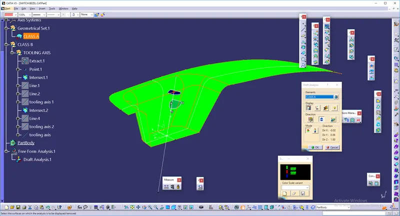
- After opeaning the draft analysis tool
we have to click on the compass which is oresent in draft analysis table and find the compass , drag it towards the tooling axis and design them
click on the lock box then ("x") thhis symbol will arise , go to the object and click on them .
we can measure the angle of object by clicking on the eye symbol which is present on the display .
we can get the result by clicking options which are present on the model .
image showing draft analysis of class a surface
after that we have to creat a class b surface by using the extract , untrim , extrapolate , trim ,join and sweep .at first we have to creat the Class B .
after creating the class b we have to take the class A and we have to use the boundry so that we can creat the class C by using the sweep command with the help of the tooling axis .
since the three surfaces are created we have to combine them with the help of the trim options . after combining the surfaces we should go topart work bench so that we could use thickning command to form a solid body .
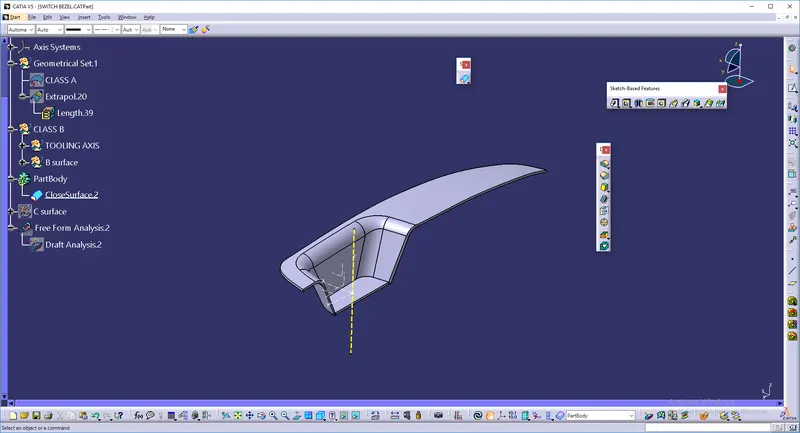
after the formation of the solid body we need to do draft analysis as said above .
draft images are shown below
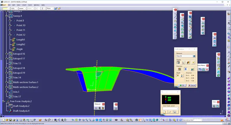
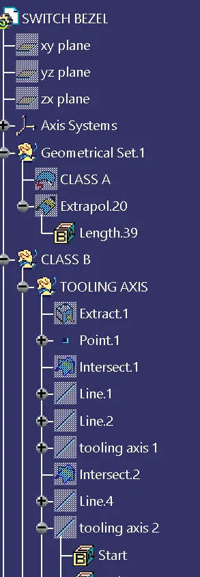
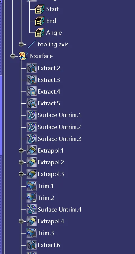
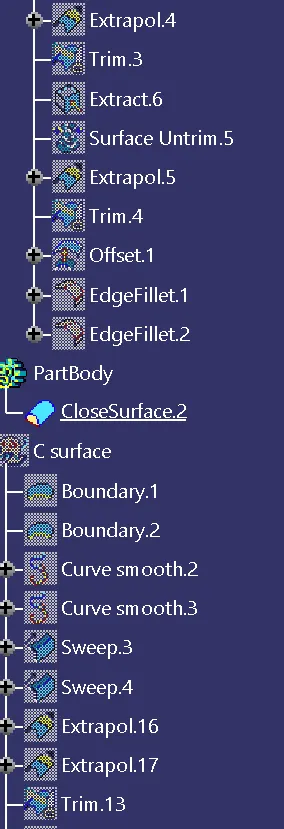
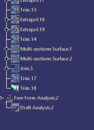
tree images are shown hear ::