Week 8 - Challenge 3 - Switch Bezel Design
DESIGN OF SWITCH BEZEL PLASTIC COMPONENT
AIM: To create the Switch Bezel Plastic component with a thickness of 2.5mm through the given Class-A surface beginning with the tooling axis should be created meeting the requirements of the draft angle and again performing the Draft analysis on the model.
PROCEDURE:
Draft Analysis:
While performing the operation, the molded cavity should be safely removed from the core to avoid damages to the surface of the parts and the tool. To avoid this, the draft angle is maintained at a certain degree which is not perpendicular(90 degrees) between the part and the tool. No parts can be ejected from the tool if it is having a straight 90 degree profile from its base surface. A small draft angle is provided to each and every area of the component in order to get an easy removal of the component from the tool.
Draft analysis technique is used to analyze whether our part model created in cad is manufacture based on the draft condition applied. Here the part should get easily removed from the panel dies in case of Sheet metal part or Mold in case of plastic. Here we are providing a direction in which components should eject in order to get an easy removal of components from the tool. In other words it also lets us know whether the model is having a draft angle and how much is the draft angle from the tool direction.
Tooling Axis:
The tooling axis is the method which decides whether the tool enters into mould or not as as it denotes the draft clearance angle where a molded part is easily removed from the mould.
Procedure for creating tool axis:
- Firstly, we will be given a class A surface for the switch bezel component which is looked as aesthetic and a smooth finish which is created with an Alias software workbench which is also known as a free imagination surface.
- For that class A surface, we need to check the boundaries first to check whether any unattached faces are present in that surface.
- We have to find the easy axis creation from that class-A surface and build the dummy tooling axis of X and Y direction and thereby creating the Tooling axis in Z direction.
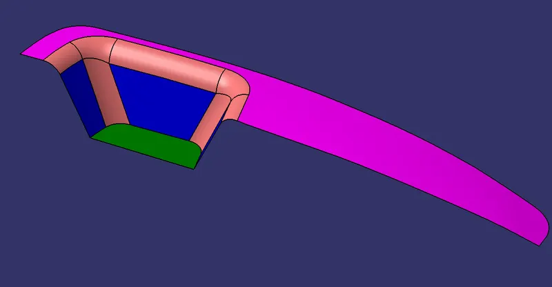
- The below is the image of a class A surface which is given as an input.
- The dummy tooling axis is created by means of bisecting method with the help intersecting the class-A surface with the respective plane.
- With the help of the inclined lines to the surfaces, we have to assume that the draft required is the result of the main tooling axis.
- Then we intersect the both the lines and the bisecting line will be the tooling axis.
- Below is the image of the tooling axis.
- The publication option helps the user to find the geometrical set whatever we have created in tree structure.
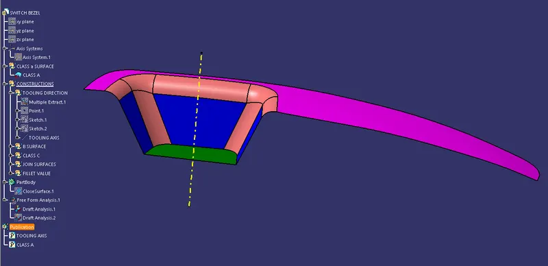
Here the tooling clearing Y direction is created with the help of bisecting method intersecting the supports with reference to the yz plane and another tooling clearing X direction is created with the help of zx plane. With the help of these two tooling clearing directions, the main tooling axis is created which is the tooling direction.
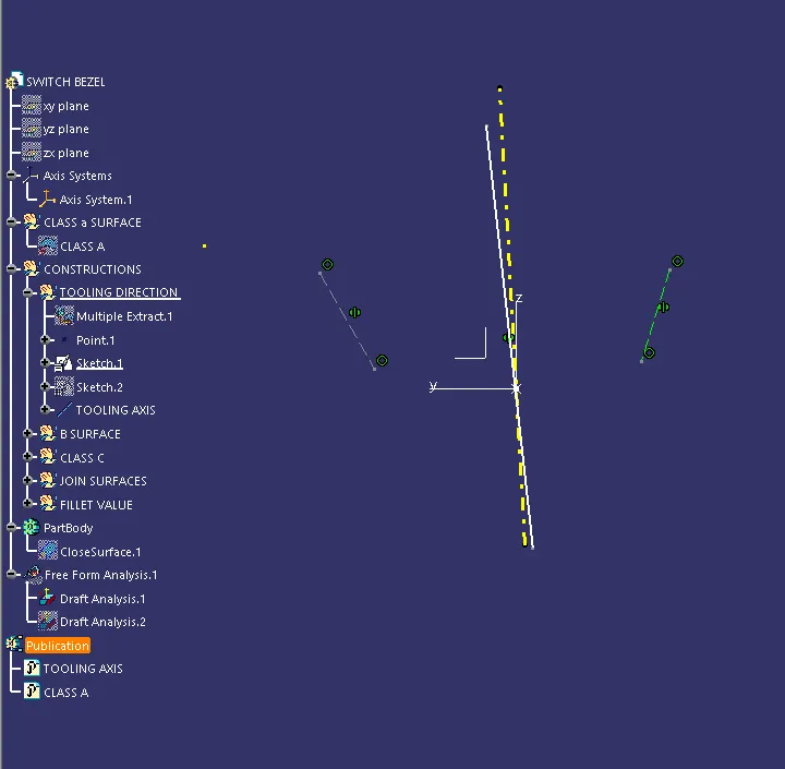
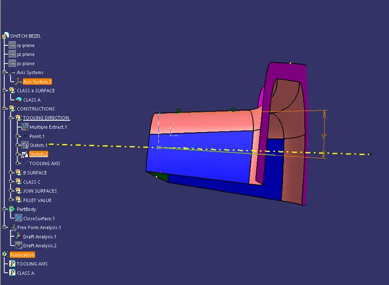
Procedure for Draft Analysis:
- Change the view mode to Customize View Parameters and select Material option from the Mesh. Next we need to get the compass and place it on the tooling axis.
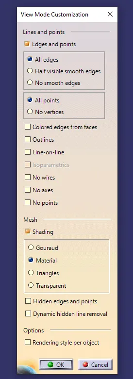
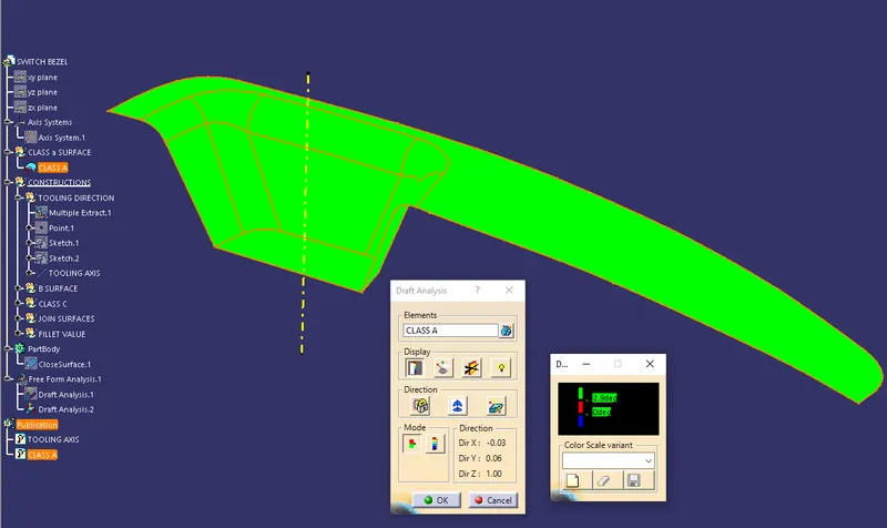
Click the Draft Analysis icon or choose the Insert > Analyze > Draft Analysis menu command.
- It is assumed that the mold will be pulled along the Z axis. You can change the Pull Direction in the Control Panel, or click and drag the Direction and Origin handles in the modeling views.
- Draft Analysis dialog box with colour scale (with quick analysis mode) appears on the screen. So the first mode option is the quick analysis mode and second is full analysis mode. Here the quick analysis mode is used.
- Change the value of green according to the draft angle provided to the part.
- To get a clear picture, either we need to adjust the compass by holding the marked region of the compass and dragging it towards the opposite direction or by selecting the inverse draft direction option inside the direction of Draft Analysis.
- After getting green colour on the component, try to adjust the compass using the knob, and adjust the direction of the compass to get green on the entire top panel region.
- Try zoom in and check if each and every region of the panel is showing green, if in some region, red or blue is showing instead of green.
- If there are any errors found, we need to adjust the compass direction to optimize the errors.
- If there is any error that is unable to change we need to use the side cores for that position.
Surface Model Creation:
So from the class A surface we need to get the extracts and offset them to get the exact replica of the class A surface. Below are the images of the surface model creation.
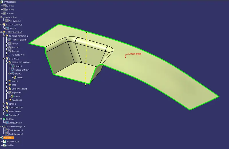
So after the offset is done trim operation is done to get the class B surface.
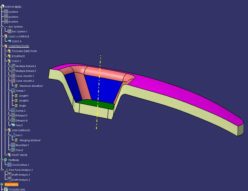
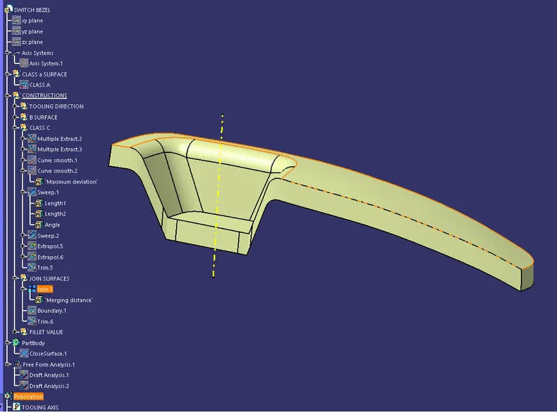
To find the class C surface we have to apply a Sweep operation for class A surface and we have to apply trim operation for the class-A surface. The join operation is used to join the class-A and class-C surface and then the boundary operation is performed to find the open surface. The merging distance should not be exceeded to 0.003mm.
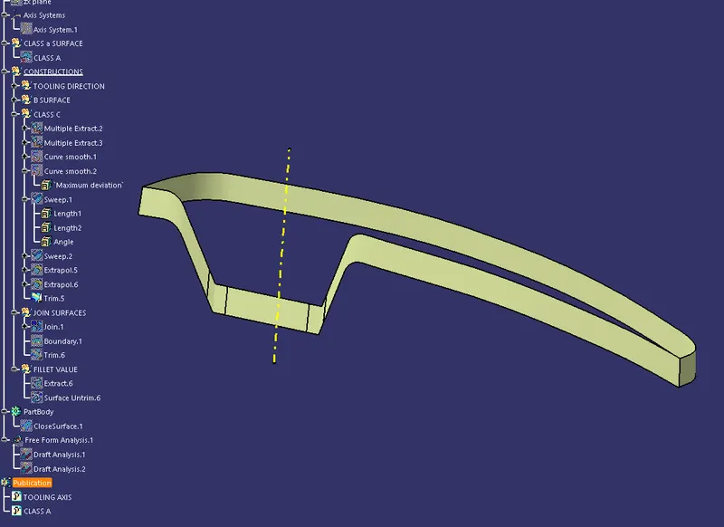
The above image is the class-C surface after sweep and trim operation.
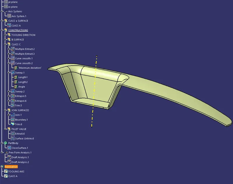
The trim operation is performed to the remove the extra surfaces for all the class -B and class C surfaces. After creating a closed surface, we need to give a body for that closed surface using a closed volume tool in the part workbench.
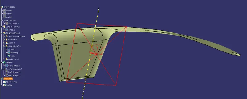
After defining in the part workbench, the closed surface is applied on the hollow surface.
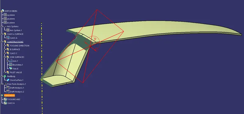
We need to check the draft again to conform to the part for manufacturing which is class D.
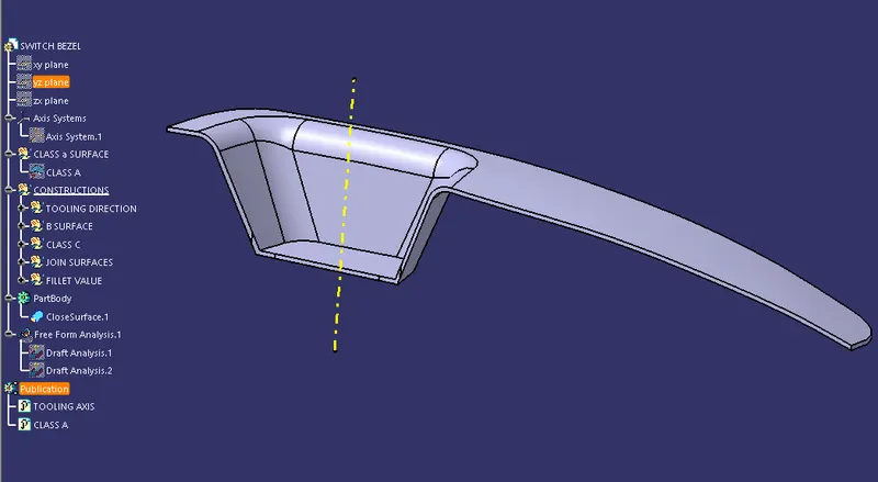
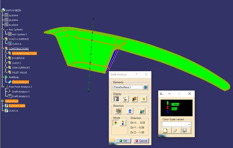
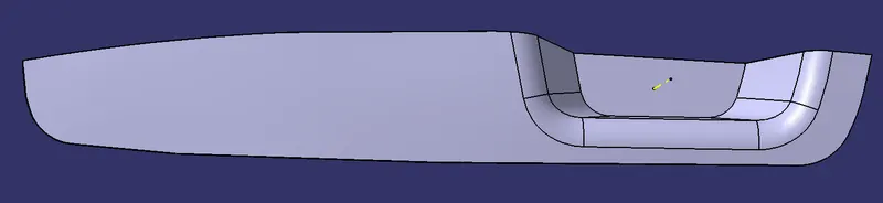
Solid model with the proper color code of the draft angle in various orientations
Isometric View
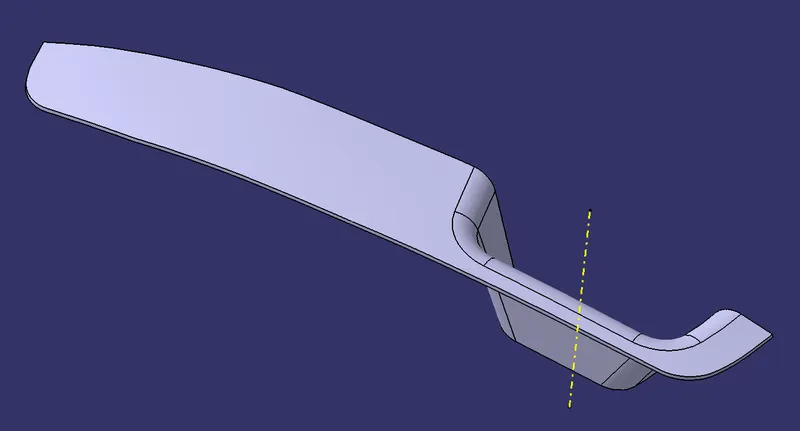
Front view
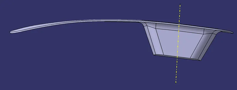
Side view
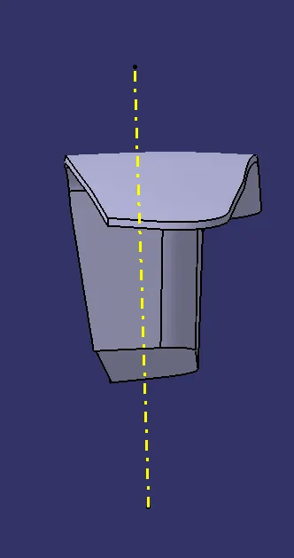
Top view
CONCLUSION :
After performing the draft check for the final product, the angle of 2.9 is the degree where the tooling axis is finalized.
Google Drive Link: