Week 8 - Challenge 3 - Switch Bezel Design
Switch Bezel Design
- Report
- A detailed report should be done explaining the draft analysis and the tooling axis creation.
- The draft analysis is done for the Class A Surface & Closed solid surface.
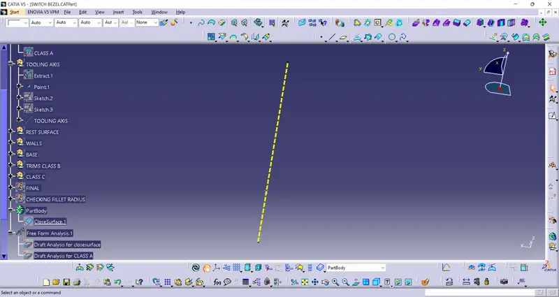
- To perform draft analysis we need to have a tooling axis to alligne the compass direction.
- Tooling axis is the one where core & cavity moves along it.
- We create it based of the draft needed.
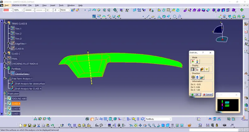
- For the class A surface after draft analysis we can see that the indication is green which implies the angles made are above 3 deg as shown in color scale.
- If angles is between 0 to 3 deg it is indicated by color pink & below it is by blue.
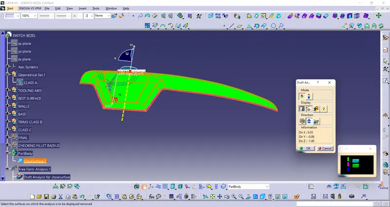
- Similarlly for Closed surface draft analysis we can see different color indications based on the angle mentioned in the color scale.
DRAFT ANALYSIS ON CLASS A SURFACE
Inetially all surfaces were not getting cleared so we alligned the tooling axis so that all surfaces are cleared.
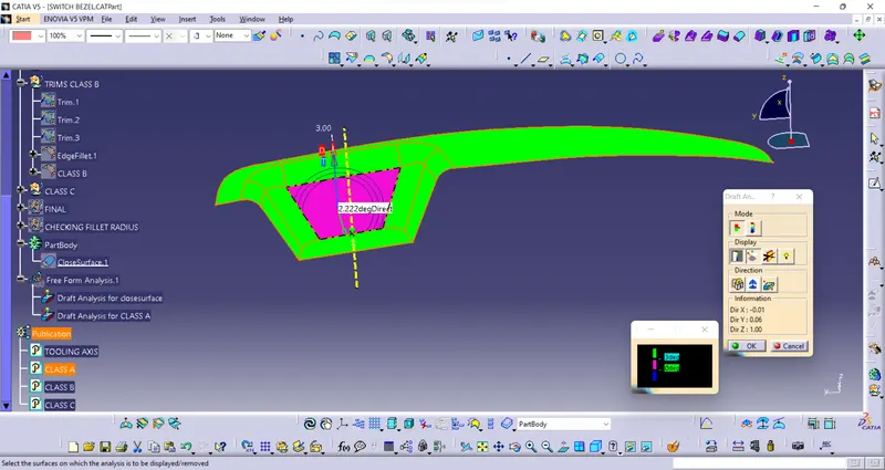
After allining tooling axis
DRAFT ANALYSIS ON CLOSE SURFACE
- An explanation should be given on the way of creating the tooling axis particularly the Bisecting method.
- First we extract the Base surface by the extract command
- The point is place on a surface of extracted base surface centre(0mm).
- We insert the axis system on a point which is alligned to the current axis system.
- We sketch to get the Tooling axis in X & Y by intersecting 3D element.
- Finally,by bisecting line command we bisect axis from X & Y.
- Thus, we get the Tooling axis.(It is the axis on which Core & cavity Moves)