Week 8 - Challenge 3 - Switch Bezel Design
Draft analysis:
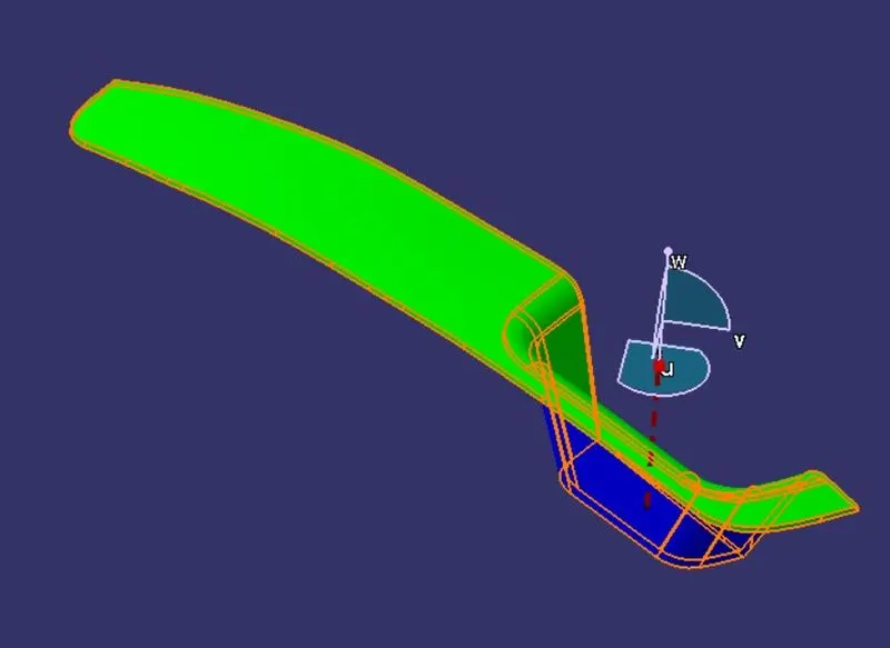
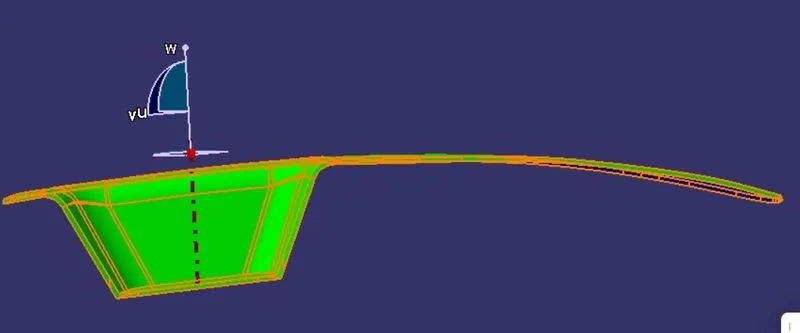
The Draft Analysis command enables you to detect if the part you drafted will be easily removed. This type of analysis is performed based on color ranges identifying zones on the analyzed element where the deviation from the draft direction at any point, corresponds to specified values.
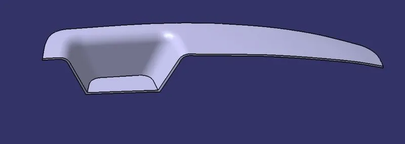
Class A surface
First import the class A surface provided into the catia V5 software
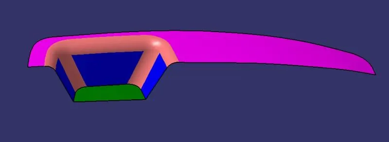
To create a tooling axis in x axis the intersection command used to get a intersecting line.
Then using those line the tooling axis for x axis created.
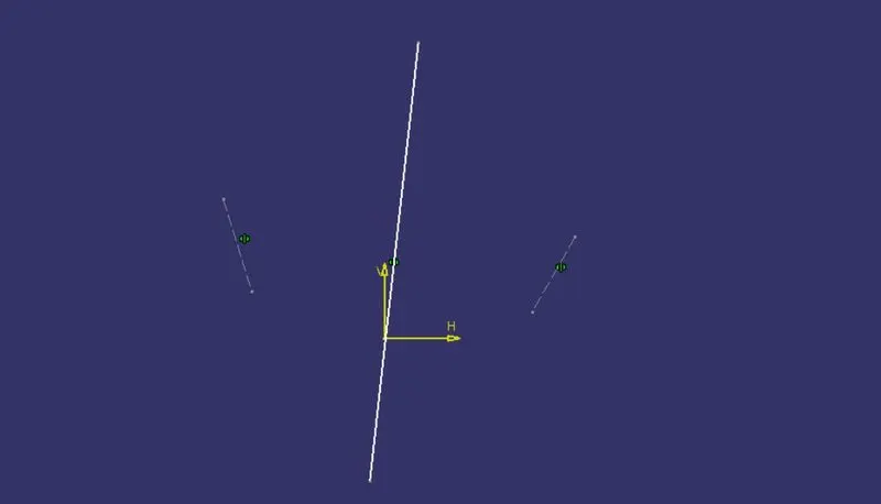
Tooling axis for y axis with 6 degree.
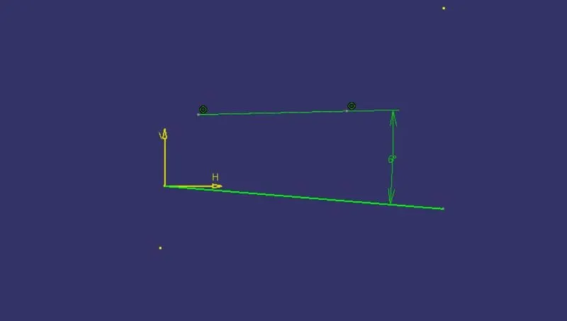
By using this two tooling axis the main tooling axis was created using bisecting line method
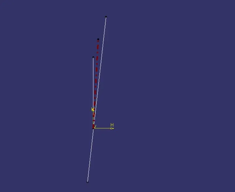
Then to create class B surface the required surfaces extracted then project it with 2.5 mm thickness.
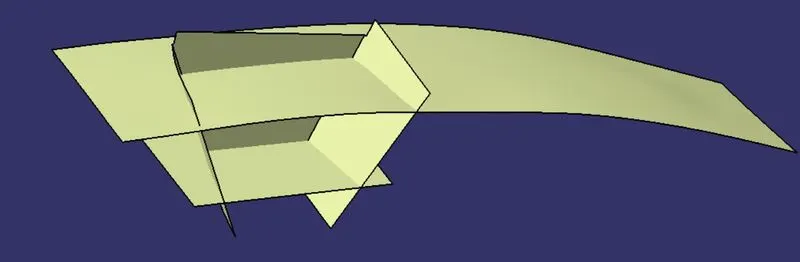
After trimming those surfaces the desired class B surface was created.
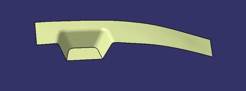
To create class C surface the boundry of a class A surface was created using boundry command.
Then the boundry line was sweept along the tooling axis.
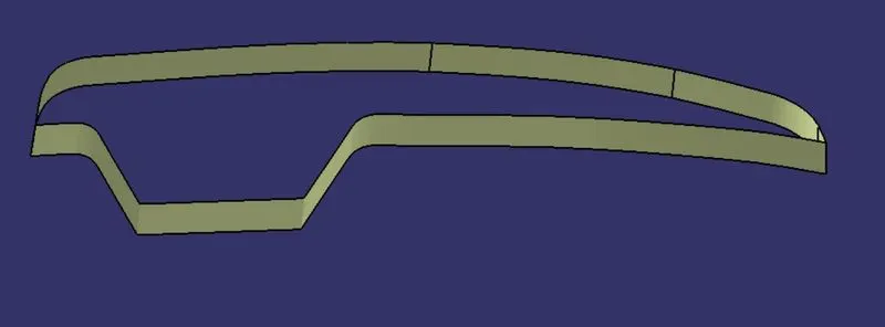
The class A and class C surfaces were joined.
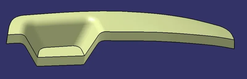
By using class B surface the joined surface was trimmed to get a final surface model.
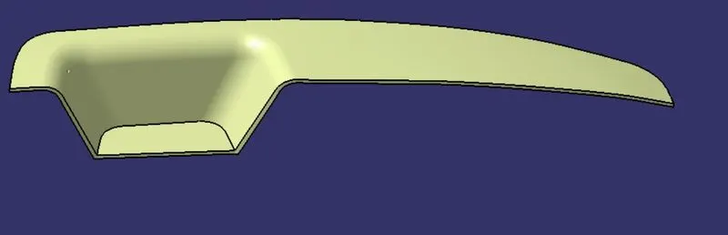
Then this surface model converted into solid by using close surface command.
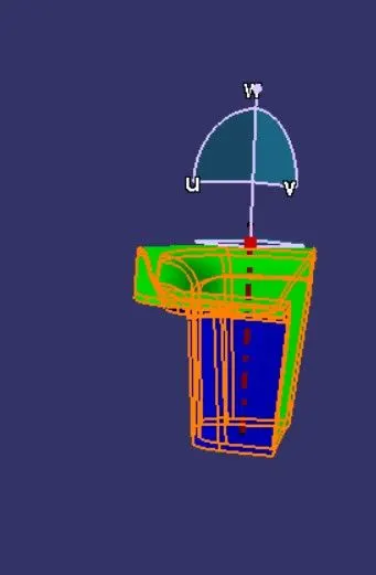
Dreft analysis
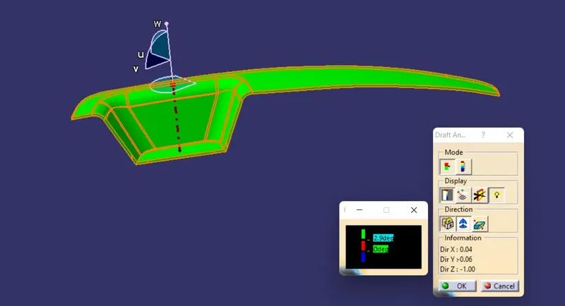
Various views for draft analysis
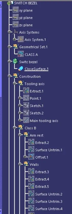
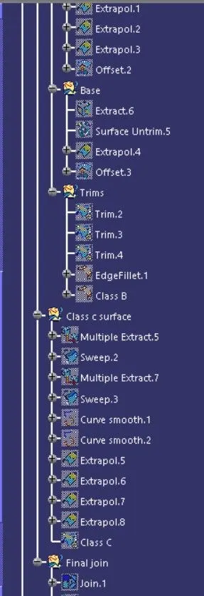
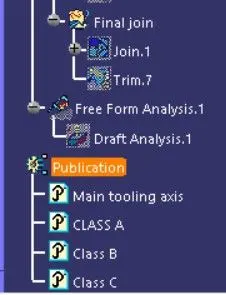
Tree stucture