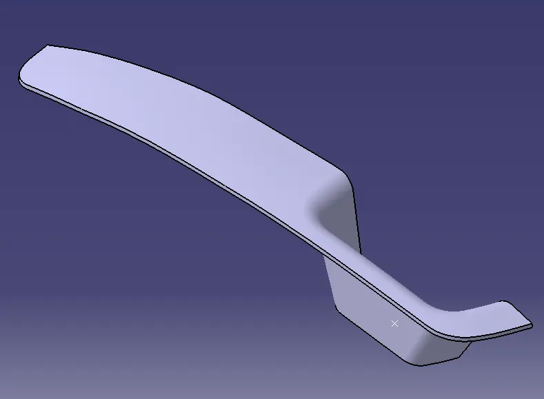
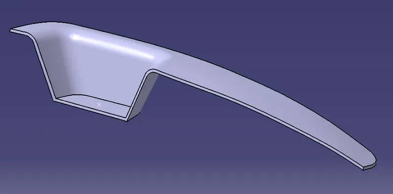
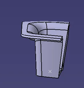
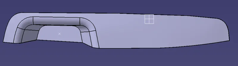
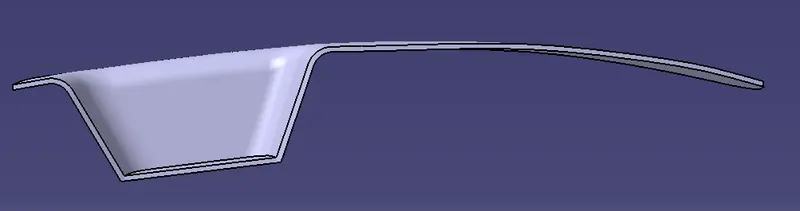
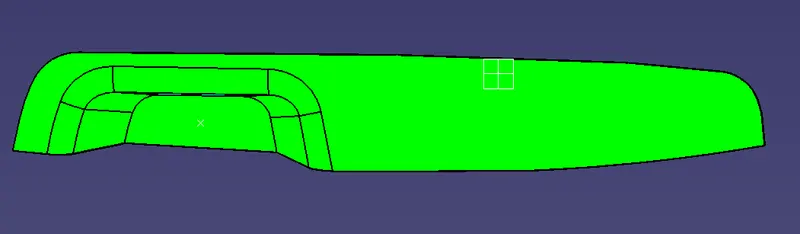
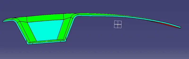
Week 8 - Challenge 3 - Switch Bezel Design
SWITCH BEZEL TOOLING DIRECTION
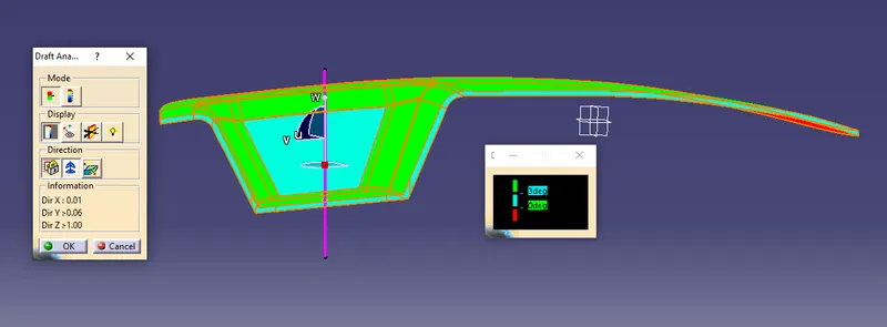
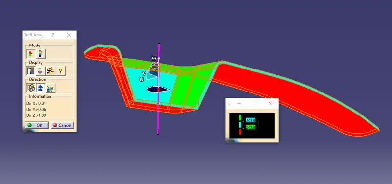
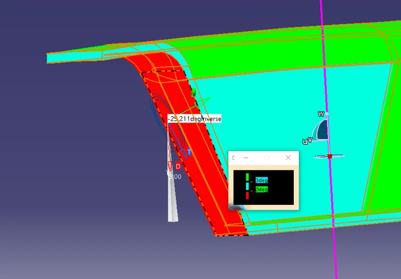
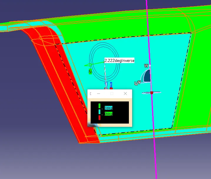
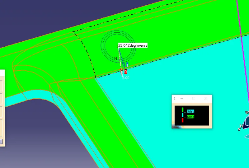
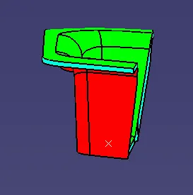
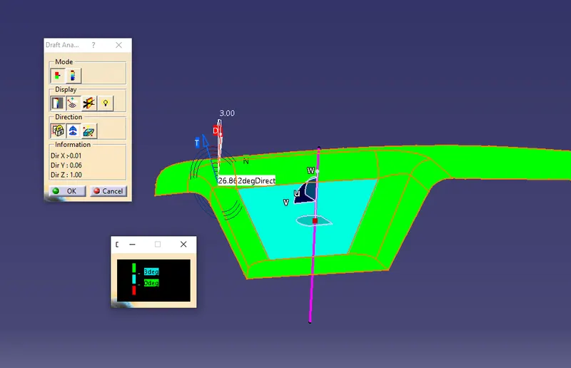
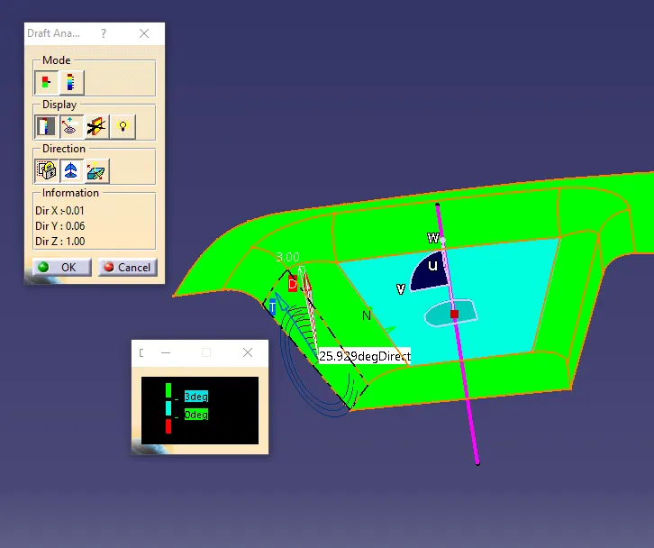
- First, the Class A surface is checked from all possible directions to get the draft angle
- This is checked to get the best possible draft without compromising the acual structure
- The axis to be drafted is slected and a point is placed on the centre of the face
- A line is drawn intersecting the point to get a dummy tooling axis
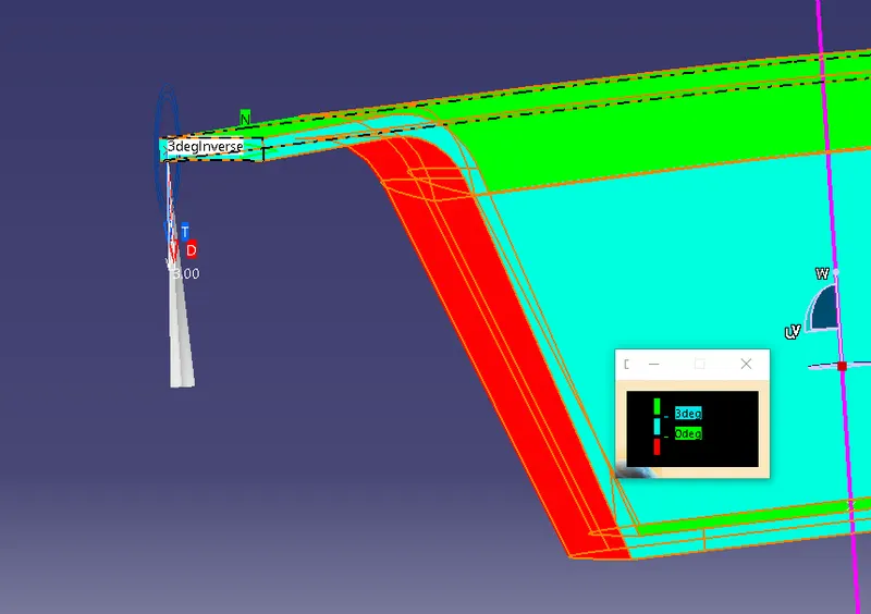
- Now, the side walls where draft might be an issue is selected
- A positioned sketch is created at the given point and an intersection is created along the y axis
- Two lines are drawn on the side walls which is then made into a single line using Bisecting line option
- The same steps are done along the X Axis to get another bisecting line on the given point
- Now, the 2 lines are bisected to create a 3rd line which is the tooling direction for the given structure
- This tooling axis allows the user to perform draft analysis and to check if the component is ok for further creation
CLASS B AND CLASS C SURFACE