Week 8 - Challenge 3 - Switch Bezel Design
Draft analysis on Switch bezel
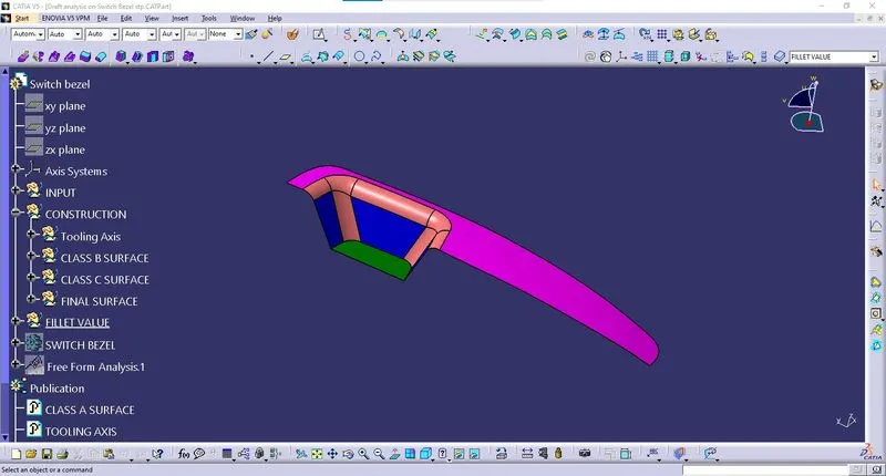
1. Creation of Tooling Axis:
Tooling Line along Y axis:
Intersecting lines are created from the class A surface along the Y sketch plane. A bisecting line is created as shown.
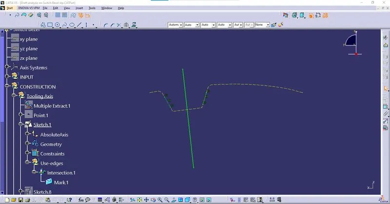
Tooling Line along X axis:
A Tooling line of 6 deg is created, as there is no wall on opposite side to create a bisecting line.
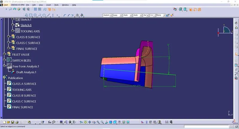
Tooling Axis by Bisecting method:
Publish the Tooling Axis and class A surface.
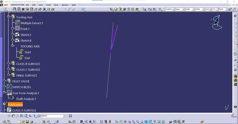
2. Draft Analysis on Class A surface:
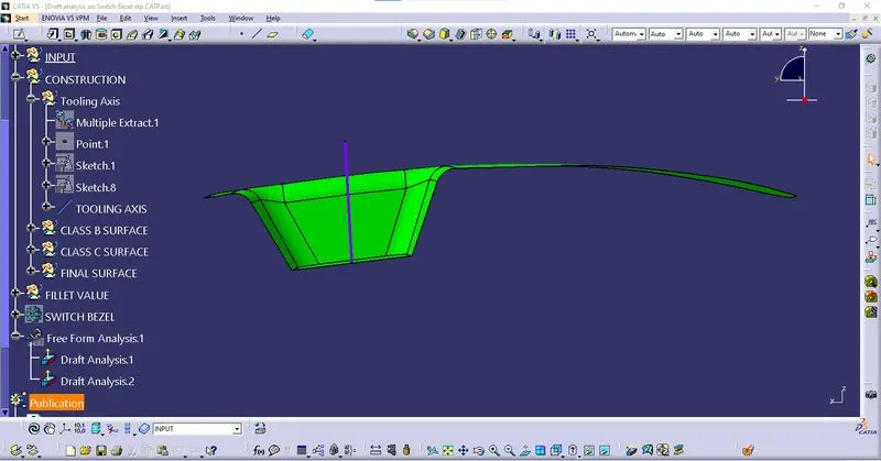
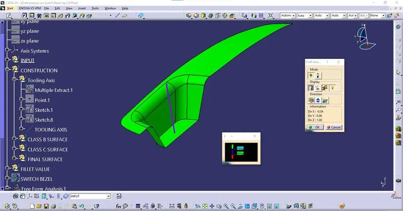
From the Draft analysis it is clear that the Tooling axis is in correct direction for the mold to open and eject the component.
Color scale
- Green – Draft angle is greater than 3 Deg
- Blue – Draft angle is between 0 & 3 Deg
- Red – Draft angle is less than 0 Deg
3. Creating Class B and C Surface:
These surfaces are created by
- Extracting surface from Class A surface.
- Untrim the Extracted surface.
- Extrapolating the surfaces.
- Trimming the surfaces together.
Class B surface:
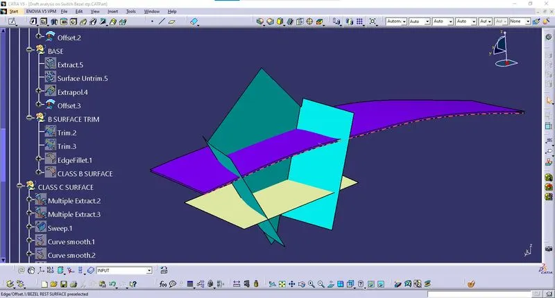
This surface is created by various surfaces from class A surface.
- Bezel rest surface
- Walls
- Base
- B surface Trim
Make sure the Thickness of Class B surface from Class A surface is 2.5 mm, give proper fillet value to maintain the Thickness.
Class C surface
Created by
- Multiple Extract
- Sweep
- Smooth curve
- Extrapolate & Trim
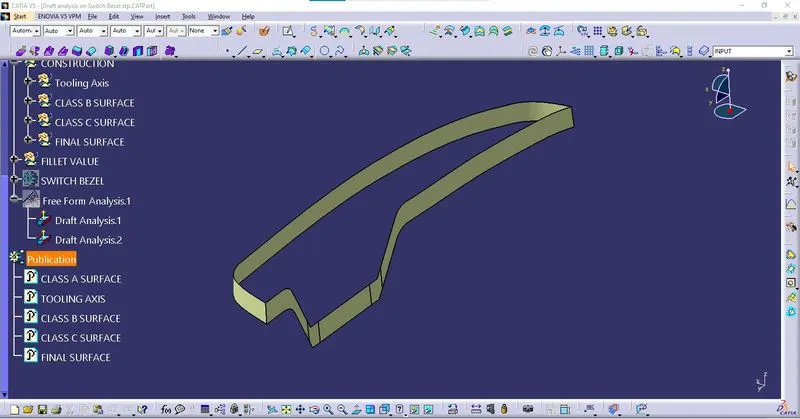
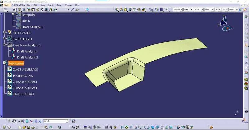
Final surface
Closed surface is formed by Trim & joining the Class A, B & C surfaces.
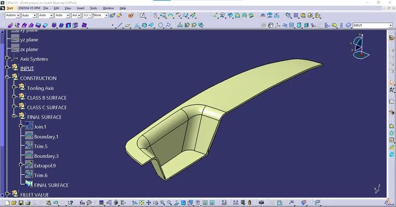
Check the Final surface for gap using Boundary Option
4. Create Part using Closed surface
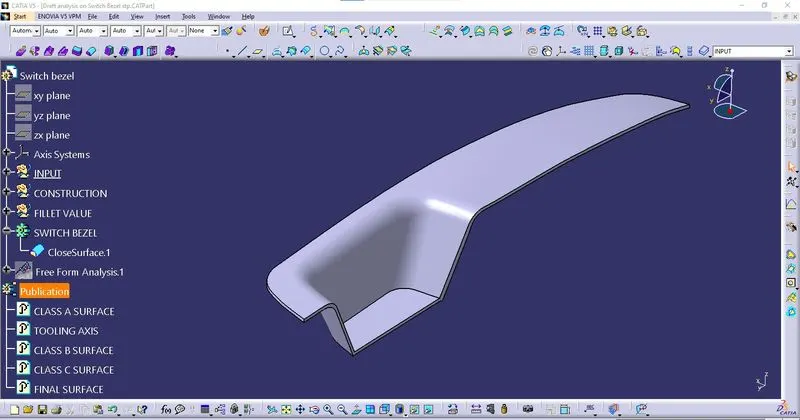
5.Draft analysis on Part
Perform draft analysis on Part along Tooling axis
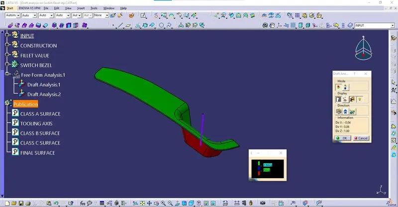
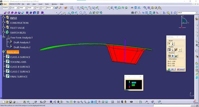
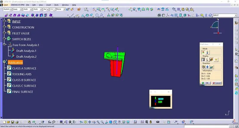
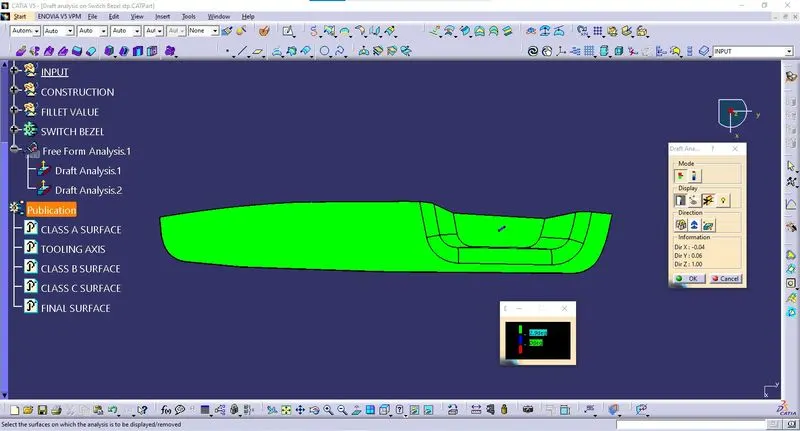
Color scale
Green – Greater than 2.9 and above
Blue – Between 0 & 2.9 Deg
Red – Less than 0 Deg
The Draft analysis concludes that the tool can clear along the Tooling Axis of switch bezel.