Photo Realistic Rendering of American Chopper
MODELLING AMERICAN CHOPPER USING SOLIDWORKS
OBJECTIVE:
- To model various parts of American Chopper in Solidworks PART.
- Assemble the parts of American Chopper in Solidworks ASSEMBLY.
- Photorealistic rendering using Solidworks PHOTOVIEW 360 and Solidworks VISUALIZE.
In this project we will be understanding basic knowledge on Part modelling , Assembly and Photorealistic rendering from intermediate to some advanced level, all in Solidworks. It will also serve us, as a guidance to interpret with solidworks in a efficient and practical manner to achieve our desired objectives and results, and also an Interesting project to start with for a Beginner in Solidworks.
DESIGN METHODOLOGY/APPROACH:
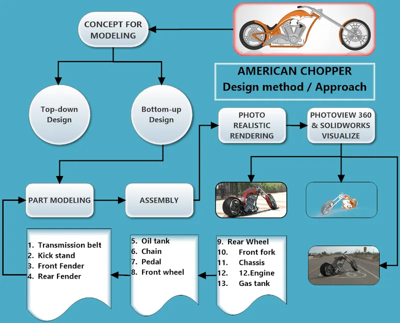
PARTS MODELLING FOR AMERICAN CHOPPER:
- Transmission belt
- Kick stand
- Front Fender
- Rear Fender
- Oil tank
- Chain
- Pedal
- Front wheel
- Rear Wheel
- Front fork
- Chassis
- Engine
- Gas tank
1.Transmission belt: It is used to transmit power from Engine to Gear Box.
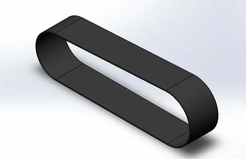
Features used:
- sketch
- Offset entities
- Extrude
- Fillet
- Appearances
- sketch
 :It is used to create two dimensional images on a plane.The images are drawn with the help of varoius sketching tools like Line, Circle, Spline, Arc, polygon etc.
- Offset
 :It is used to offset entities by specifying distance either from one direction or in both directions.
- Extrude
 :Helps to convert 2D sketch in to a 3D solid.
- Fillet
 :It helps to round the sharp edges of solid or surface faces to the specified radius.
- Appearances
 :It gives color and texture to the part without affecting physical properties.
Procedures to create the model:
- Open solidworks.clik New, select Part
 and then click ok.
 - Select front plane, click on sketch tool.
- Draw the 2D sketch with proper dimensions and relations to fully define it (sketch turns black).
- Exit the sektch, select extrude boss/base from Features, add dimensions to create solid model.
- Add fillet as required.
- Save the part as Transmission belt.
2.Kick stand:Helps to park the bike.It is attached to chasis.
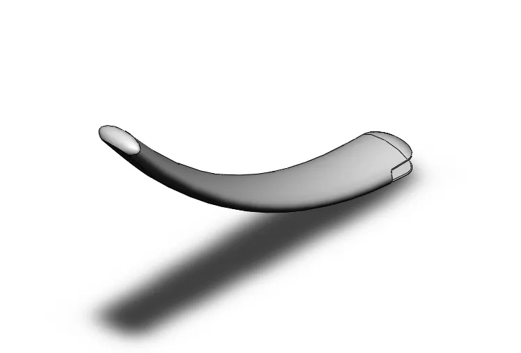
Features used:
- Sketch
- Loft
- Dome
- Extrude boss
- Extrude cut
- Fillet
- Split
- Appearances
- Loft
 :Helps to create a shape by making transitions between multiple profiles and guide curves. This tool is very valuable for modeling complex surfaces.
- Dome
 : It creates a dome that is tangent to the adjacent cylindrical or conical face.
- Extrude cut
 :It is used to cut material from a part.
- Split
 :It is used to create multiple parts from an existing part i.e split the part in to two or more depending on the requirement, with an option to remove or keep the selected bodies as well.
3.Front fender:Front fender protects the rider and other parts of the chopper from mud and dirt.It is mounted above the front wheel of chopper.
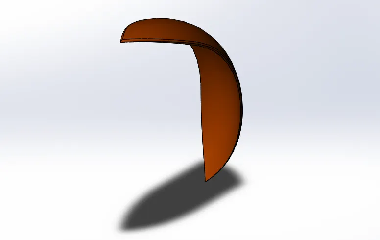
Features used:
- Sketch
- Offset entities
- Trim entities
- Revolve
- Dynamic mirror
- Split
- Trim entities
 :It is used to trim or extend adjacent sketche entities depending upon varoius selections like power trim, corner, trim to closest etc.
- Revolve
 :This feature is used to revolve a 2D sketch along an Axis or Centerline.
- Dynamic mirror
 :When creating a sketch on one side of the centreline,this tool will automatically create a symmetrical shape the other side, which has the same relations as the sketch we are creating.
4.Rear fender:It is mounted above the rear wheel of chopper and it's function are same as that of front fender.
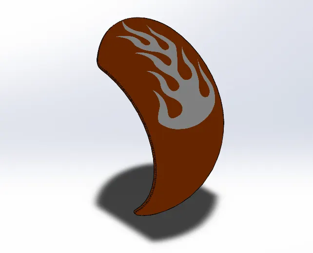
Features used:
- Sketch
- Offset entities
- Trim entities
- Revolve
- Dynamic mirror
- Split
5.Oil tank:Thi part is used to contain oil with a thickness of 3mm.
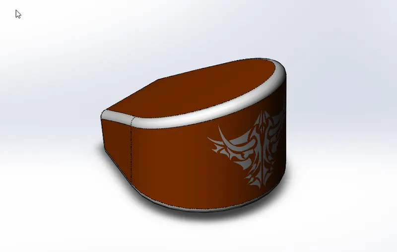
Features used:
- Sketch
- Extrude
- Combine
- Fillet
- Shell
- Appearances
- Combine
 :This tool is used to combine two or more intersecting bodies in to one solid part with add, subtract or common options to choose from.
- Shell
 :This tool hollows out a part, leaves open the faces we select, and creates thin-walled features on the remaining faces.We can also shell a part with multiple thicknesses.
6.Chain:It is a power transmitting unit from engine to rear wheel with the help of sprockets.
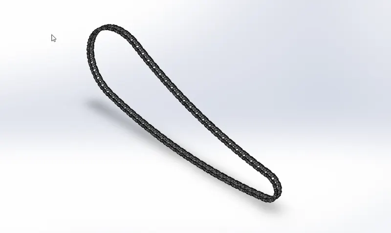
Features used:
- Sketch
- Extrude
- Trim
- Fillet
- Blocks
- Pattern
- Appearances
- Blocks

 :This tool provide a simple, but powerful method of grouping objects together. Blocks are manipulated as one object, including constraining and dimensioning as other sketch entities.
- Create sketch.
- Clik Tools > Blocks > Make > select the sketch entities > click ok.
- Select the Block and save it.
- Insert the saved block multiple times without change in constrain of each enetities.
- Patterns
 :It helps to pattern a body,face or feature along a curve which can be either open or closed.Here we have patterned the chain plates and pins as per the requirement.
7.Pedal:It is a foot rest for the rider and provides safety while riding the chopper.It is attached to the chasis.
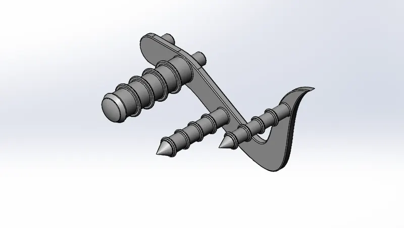
Features used:
- Sketch
- Extrude
- Trim
- Fillet
- Linear pattern
- Dome
- Chamfer
- Appearences
- Chamfer
 :This tool creates angled cut to make the corner flat.It also has many options like Angle-Distance, Distance-distance,Vertex etc.
- Linear pattern
 :It is used to drive features, faces, or bodies in a linear direction.
8.Front wheel:A solid disk connected by spokes to a hub, designed to turn around an axle passed through the center.The tyre is mounted to rim of the wheel.It is mounted to the front fork of chopper.Has disc plate attached to it.
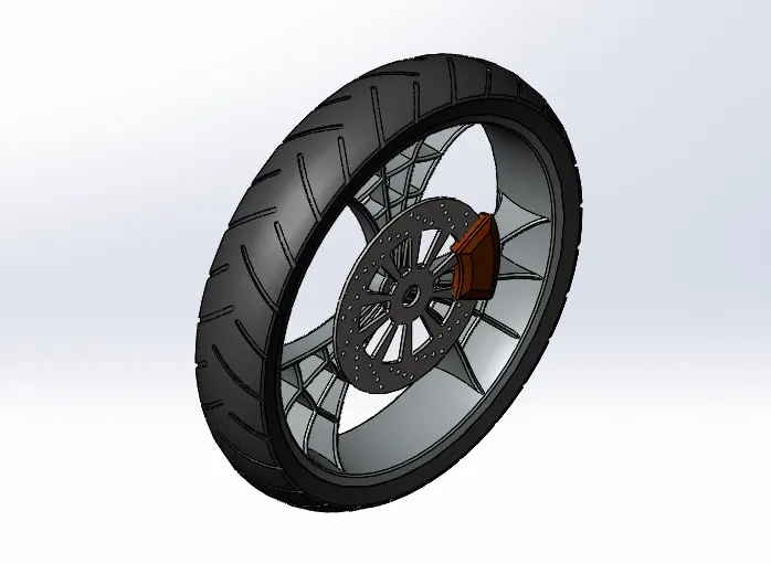
Features used:
- Sketch
- Revolve
- Trim
- Fillet entities
- Extrude
- Revolve cut
- Linear pattern
- Chamfer
- Fillet
- Extrude cut
- Circular pattern
- Appearances
- Circular Pattern
 :It is used to create rim, spokes, holes and vents on disc plate, Tyre tread etc.
9.Rear wheel:It is mounted to rear of the chasis in chopper.It has sprocket and disc plate.
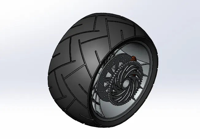
Features used:
- Sketch
- Revolve
- Trim
- Fillet entities
- Extrude
- Revolve cut
- Linear pattern
- Chamfer
- Fillet
- Extrude cut
- Circular pattern
- Appearances
10.Front fork:It is attched to front of the chasis in chopper.Has shock absorbers and front wheel is mounted in it.
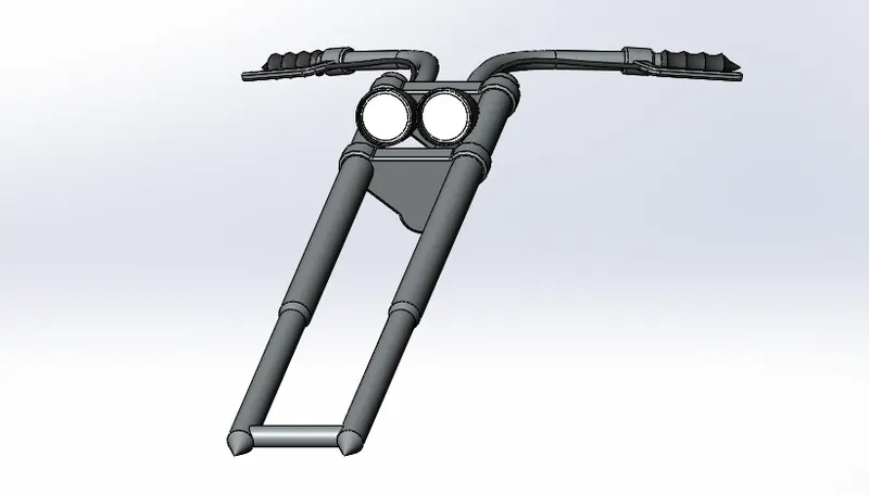
Features used:
- Sketch
- Extrude
- Revolve
- Trim
- Split
- Plane
- Move/copy body
- Dome
- Mirror
- Combine
- Project curve
- Sweep
- Appearances
- Move/copy body
 :This tool is used to move or copy a body at a specified distance or angle.
- Mirror
 :It is used to mirror features, body with respect to a plane with options to merge solids or knit surfaces.
- Project curve
 :A curve is created with respect to projection of two 2D sketch profiles.
- Sweep
 :It helps sweep a closed profile along a closed or open path.
11.Chasis:This part is where all the other parts of chopper are assembled to.It gives over all shape to chopper and forms the skeleton or frame.
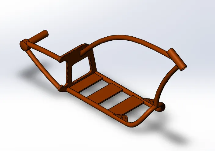
Features used:
- Sketch picture
- Sketch
- Extrude
- Offset
- Project curve
- Trim
- Plane
- Sweep
- Split
- Revolve
- Extrude cut
- Fillet
- Combine
- Appearance
- Sketch picture
 :It is used to insert an image or blueprint of model into a work plane, from which we can draw the required sketch.
12.Engine:It is mounted to the base plate, in middle of chasis.It provides the power to ride the chopper.The power from engine is transmitted to the rear wheel through Sprocket and chain assembly.
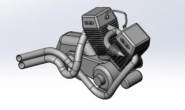
Features used:
- Sketch
- Trim
- Extrude
- Extrude cut
- Offset
- Project curve
- Offset
- Dome
- Fillet
- Composite curve
- Sweep
- Mirror
- Circular pattern
- Split
- Composite curve
 :This tool is used to create single curve by combining curves, sketch geometry, and model edges.composite curve can be used as a guide curve when creating a loft or a sweep.
12.Gas tank:Gas tank stores the fuel for chopper.It is mounted at top of chasis frame.
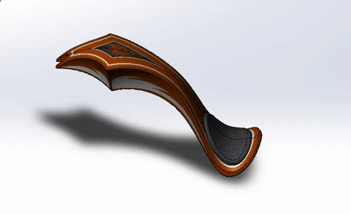
Features used:
- Sketch
- Trim
- Project curve
- Convert entities
- Swept surface
- Loft surface
- Filled surface
- Trim surface
- Knit surface
- Sweep cut
- Fillet
- Appearance
- Loft surface
 :This tool is used to create surfaces by multiple 3D Curves or existing edges creating a smooth tangency between the selected curves.Match Points are created between each selection denoting the orientation and path of the loft surface.
- Swept surface
 :It allows a 2D profile to be swept along a guide curve creating a surface.
- Filled surface
 :It is used to fill a gap in model by creating a surface.
- Trim Surface
 :It is used to trim unwanted surface using 2D or 3D profile.
- Knit surface
 :It is used to combine all the surface as one.
ASSEMBLY OF AMERICAN CHOPPER:
1.In this section we will be assembling all the parts created in solidwork with proper mate in solidworks Assembly.
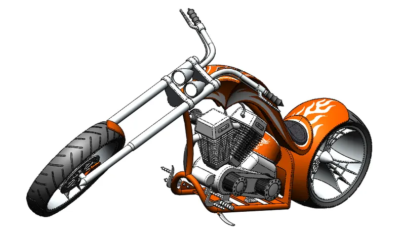
Procedure to create an assembly file in solidworks
- Open solidworks.
- Click new > select assebmly
 > click ok.
 - Insert all the parts by clicking
 .
. - After the assembly is complete, save it.
Features used in assembly:
- Mate
 :Mate has numerous function to constrain the parts assembled to work as needed.The types of mate include standard mates, advanced mates, mechanical mates.
PHOTOREALISTIC RENDERING OF AMERICAN CHOPPER:
Rendering is used to create an photorealistic image of a part, assembly, or 2D sketch with appearences, lighting, scene, decals etc.In solidworks, rendering can be done with
- Photoview 360
- Solidworks visualize
Rendered images:
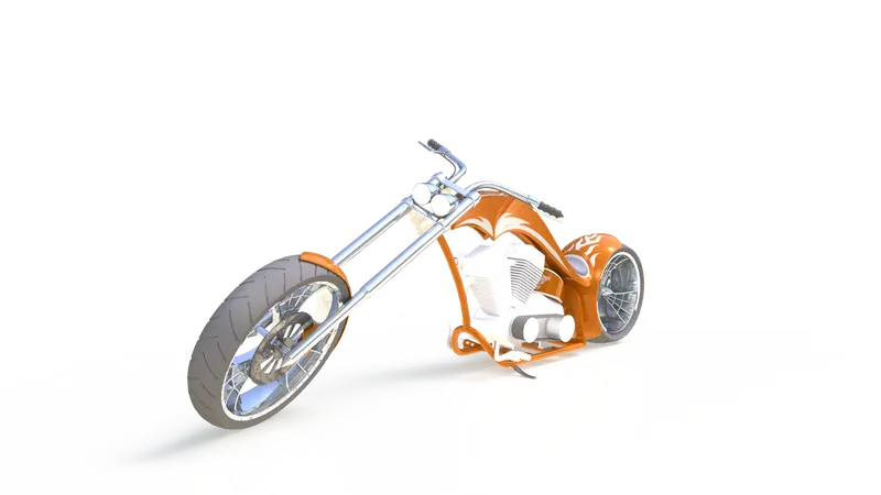
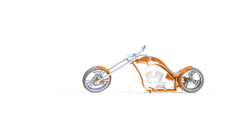
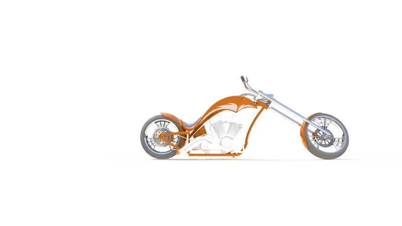
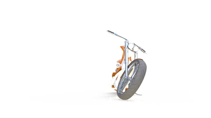
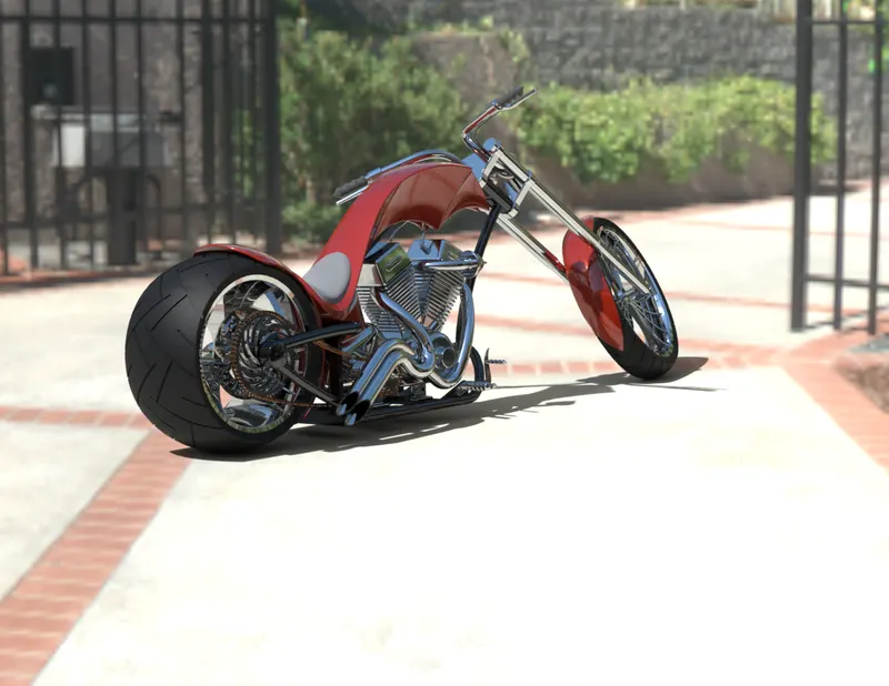
CONCLUSION:
- The above parts, assembly and rendering are done using solidworks.
- This project helps us to learn the essential tools and techniques required, which can be effectively used for our further projects in solidworks.