Week 8 - Challenge 2 - Base Bracket Design
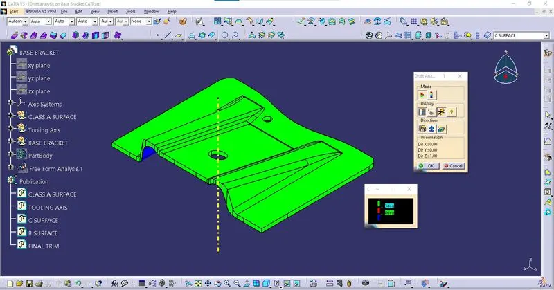
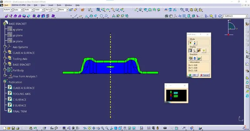
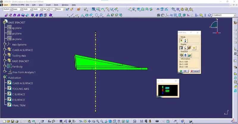
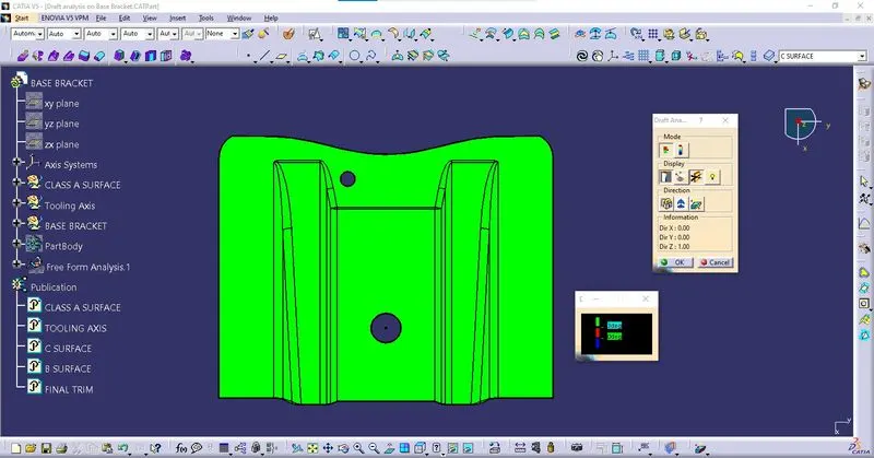
Draft analysis on Base bracket
1. Tooling axis Creation:
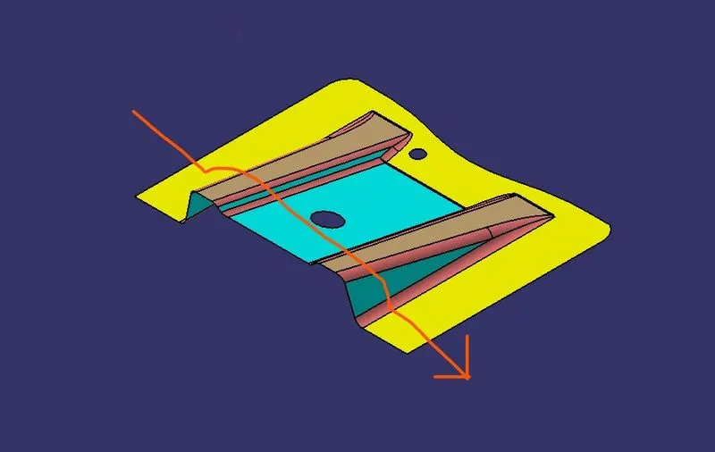
- After checking the surface along X, Y & Z direction, Z Direction is proper for tooling.
- Create a Dummy Tooling axis along Z direction.
- Create an intersection along Y axis.
- Create a Bisecting line and name it as Tooling Axis. Publish It.
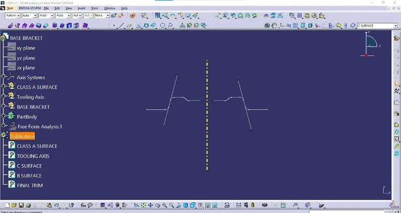
2. Draft analysis on Class A surface:
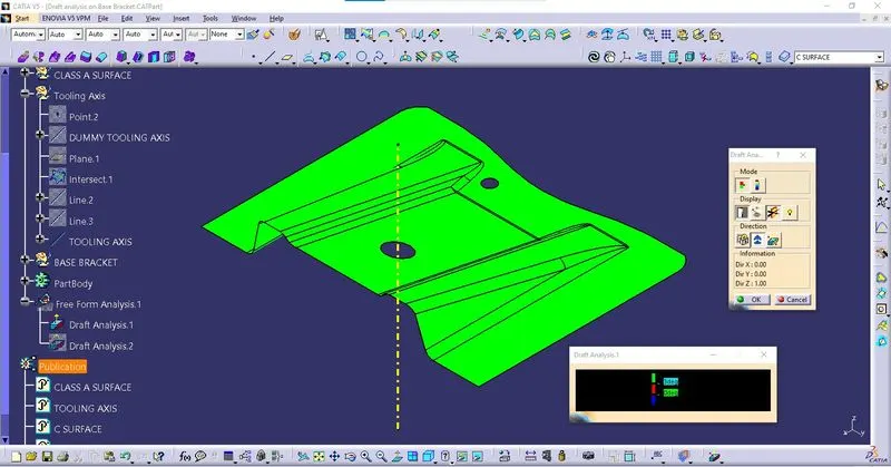
Check the surface continuity using boundary Tool.
Color scale
- Green – Surface angle greater than 3 Deg.
- Red – Surface angle between 0 & 3 Deg.
- Blue – Surface angle lesser than 0 Deg.
3. Creating Class B surface:
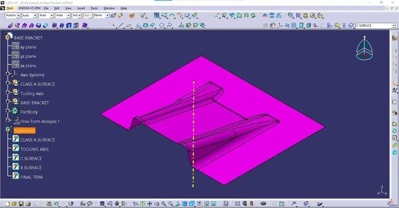
Class B surface is created by
- Extract surfaces from Class A.
- Surface untrim.
- Extrapolate
- Trim
- Offset to required Thickness.
- Publish the Class B surface.
4. Creating Class C Surface:
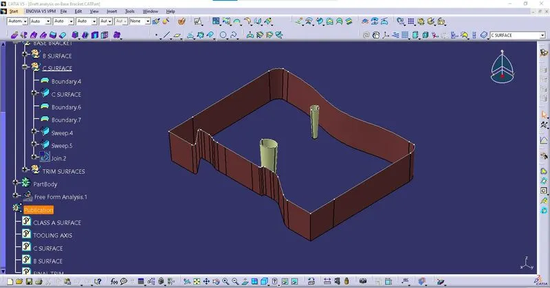
Steps to create Class C surface:
- Create Boundary from Class A surface.
- Swept surface from boundary along the tooling axis with the required draft angle.
- Publish the Class C surface.
5. Creating Final closed surface:
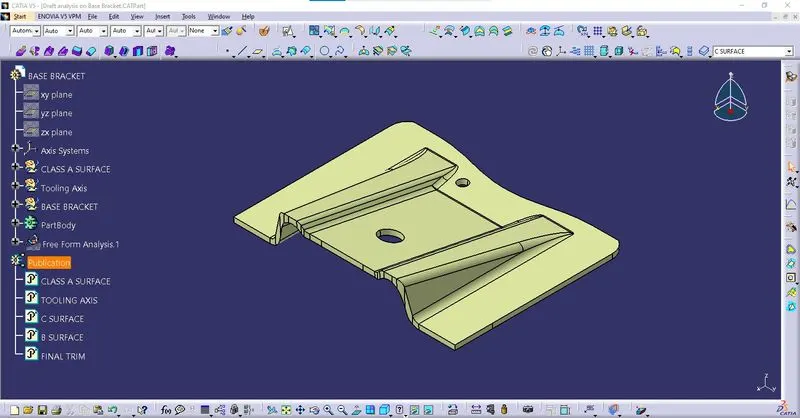
- Join class A with class C surface and trim It with Class B surface to create required closed surface.
- Check surface is closed using Boundary Tool.
- Publish the created Final closed surface.
6. Final Component:
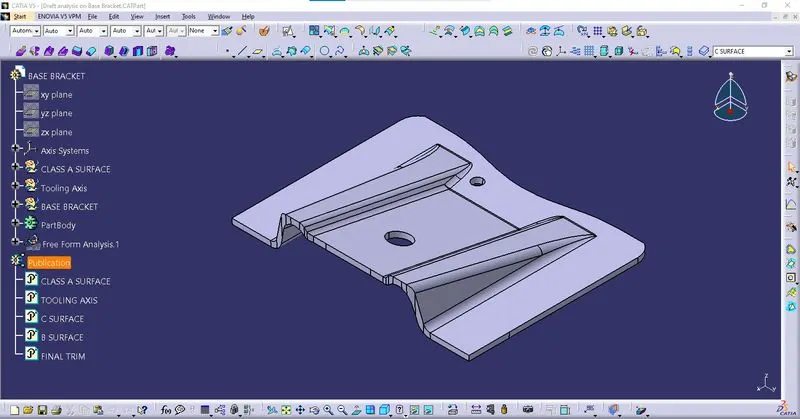
- Use closed surface tool to create solid part.
7. Draft analysis on closed surface:
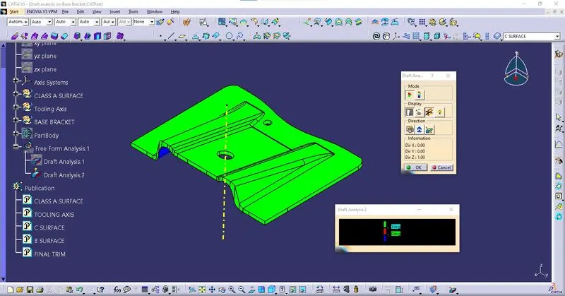
Color scale
- Green – Angle of the surface is above 3 Deg with respect to Tooling Axis
- Red – Surface angle between 0 & 3 Deg
- Blue – Surface angle less than 0 Deg and has to be corrected
ORIENTATION