Week 8 - Challenge 3 - Switch Bezel Design
OBJECTIVE:Create the Switch Bezel Plastic component through the given Class-A surface. To begin with, the tooling axis for the given Class-A Surface should be created meeting the requirements of the draft angle and at the end perform the Draft analysis on the model.
DETAILED REPORT
CLASS A SURFACE: Class-A is a term used in specifically in automotive design. It describes the final production surface data for the aesthetic parts of the car.
CLASS B SURFACE: This surface is created by taking the offset fom the class A surface and it is the surface on which all the mountings and ribs are created
CLASS C SURFACE: It is the surface which joins class A and class B together
TOOLING AXIS: It is the direction in which core and cavity opens & closes
PROCEDURE:
- check the continuity of class A surface and ensure that it was propery joined without any discontinuity.this can be done by using join or boundary comand in CATIA v5
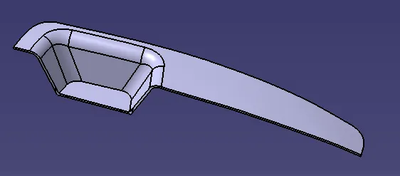
- Extracting the boundary of given class A surface and we also check continuity visually.below fig shows the continuity of class A surface
- we have to give even wall thickness to avoid flow lines after the manufacturing process
TOOLING AXIS
- to decide the dummy tooling axis direction by analyzing model visually to see which direction is most suitable for tooling axis
- We extract the base surface and create a point on the surface at center and insert axis system at the created point
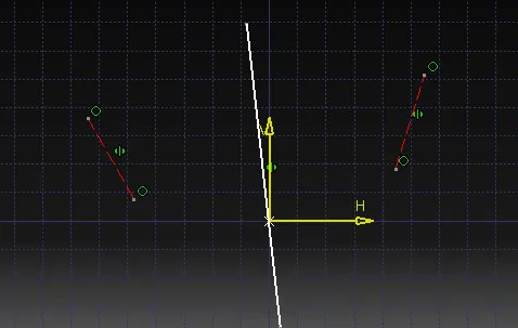
- create a sketch on YZ axis an by using intersection we created two lines and draw a bisecting line and thus we created tooling axis in y direction show in the fig
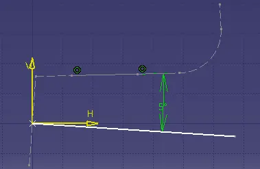
- create a sketch on ZX axis system and thus we created tooling axis in X direction and thus we get tooling axis by bisecting the two lines from above sketch
CLASS B SURFACE
- We take the simple surfaces and then untrim it and thicken those surfaces to form B surface
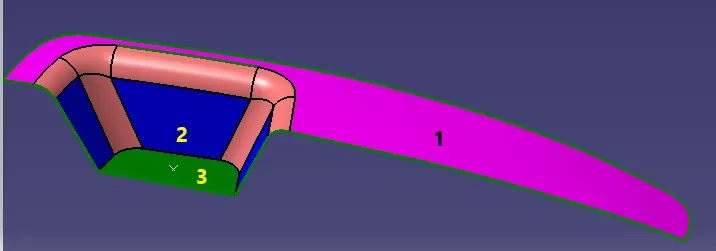
- extract the three surfaces as shown in the fig and then untrim it and for smaller surfaces to have to extrpolate it to larger surfaces
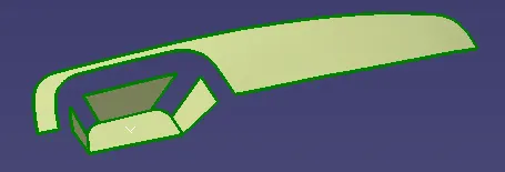
- we have to offset the surfaces to thickness 2.5 mm and the create base of bezel surface and offset it to 2.5mm
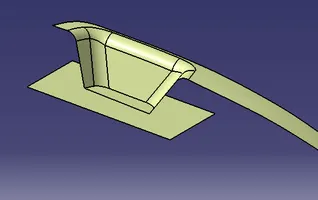
- we have trim all the extra surfaces to create CLASSB surface and give the correct fillet values to avoid the sharp edges
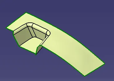
CLASS C SURFACE
- we extract the outer boundary in two parts if the class A surface and to avoid patches we use smooth curve of the extracted boundary of classs A to get smooth surface and it gives thickness to the surface
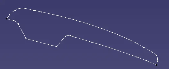
- sweep the extract boundary and then extropoalate the edges and then trim it to join the two sweep boundary and thus we created class c surface
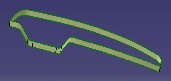
FINAL TRIM
- we join the class c surface and class a surface
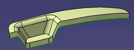
- we trim the classB surface with join of classA and class C surface
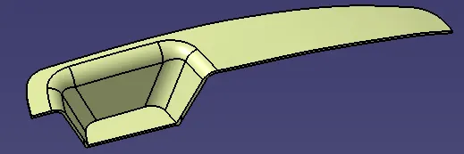
SOLID BODY
solid body was created by using closed surface in part design
DRAFT ANALYSIS
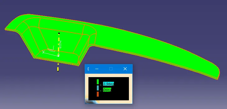
- Go to feature draft analysis and Align the tooling axis with the compass
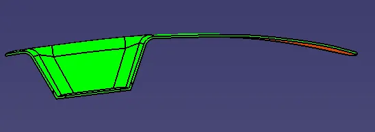
- Click on the surface and see that the surface was with in the permissible limit of draft analysis and If any surface is not green we have to edit our tooling axis
TOP VIEW
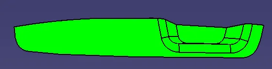
SIDE VIEW
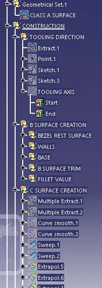
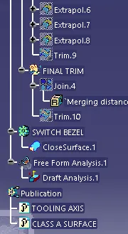
PART TREE