Week 8 - Challenge 3 - Switch Bezel Design
Design of a Switch Bezel
Objective:
- To design a Class B and Class C surface
- To create a solid part from the final surface
- To perform draft analysis on the class A surface and the solid part
Class A surface:
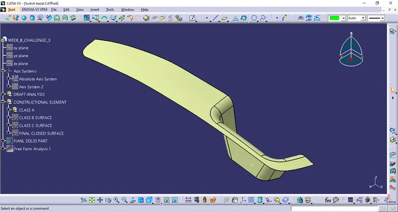
Draft analysis:
To perform draft analysis tooling axis is created.
Steps to create tooling axis:
Making tooling axis in Y - direction:
1. The surface is first extracted
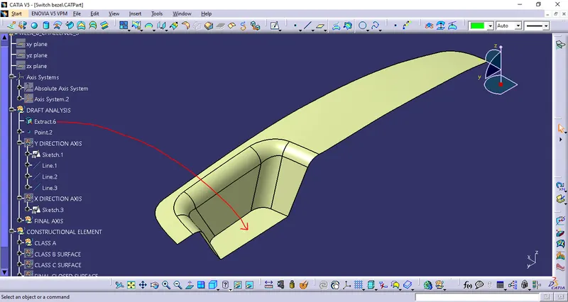
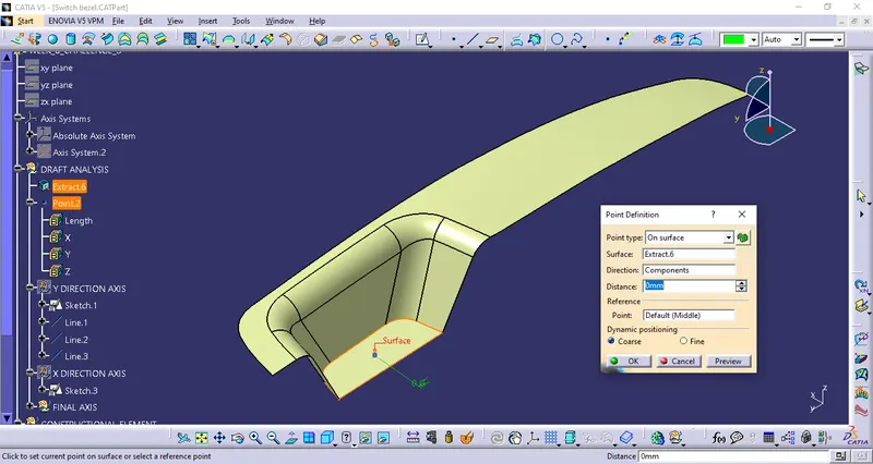
2. Point is created at the center of the surface:
3. Making new Axis system on the point and a positioned sketch on the axis system. Using intersect 3D element option make a sketch:
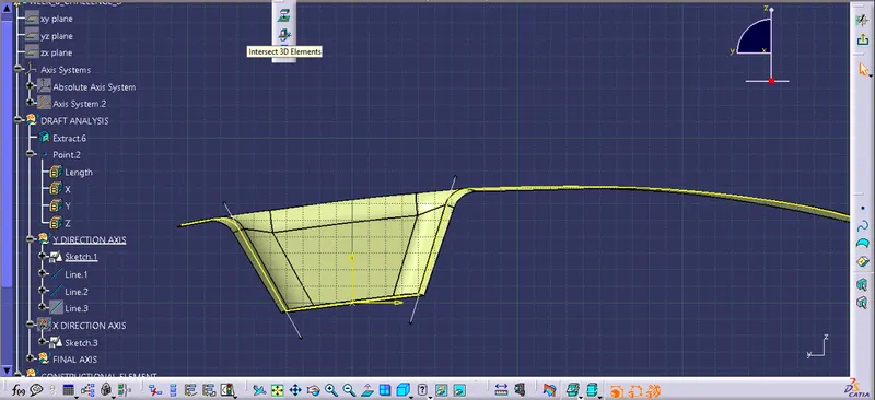
Create two lines on the vertex of the cavity:
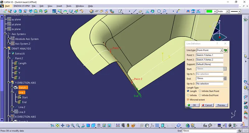
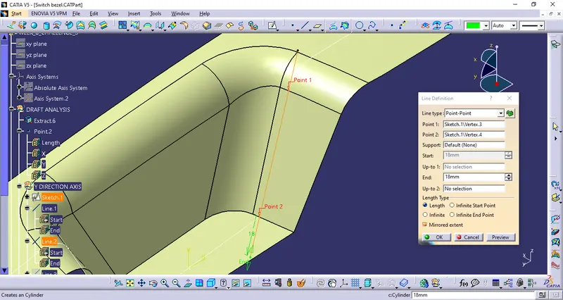
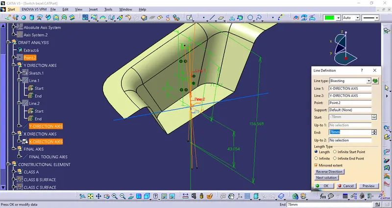
Make a ibisecting line from the given line:
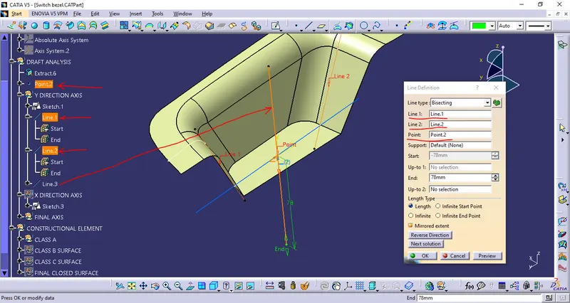
Making X - Direction tooling axis:
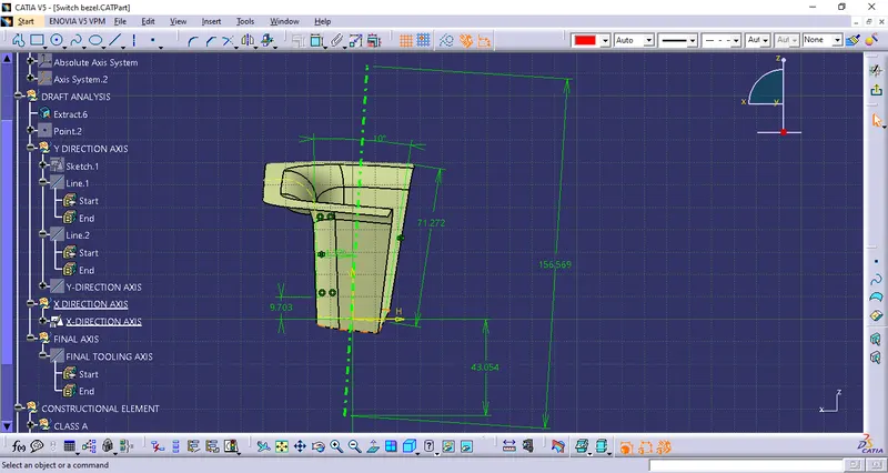
1. A positioned sketch is made on the axis system and usign intersect 3D element a sketch is made, a line is draw at an angle of 10 degree at the other end on the line. Using bisecting line option bisect the line and make a axis.
Final Tooling Axis:
The final tooling axis is made by usign Bisecting line option and making the tooling axis:
Draft analysis of class A surface:
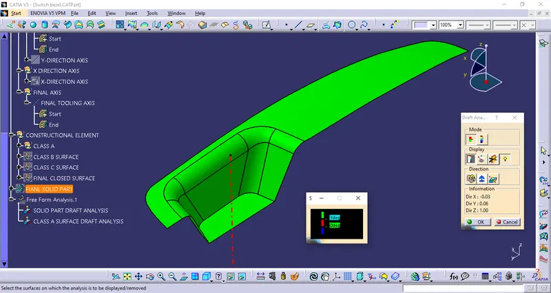
Since the class A is green the draft is positive [Minimun draft 3mm]
Making solid part:
Class B surface:
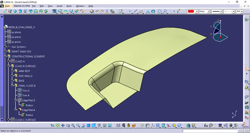
The class B surface is 2.5 mm away from the class A surface. This surface is created by untrimmig the class A, extrapolating it and then offseting surface by surface. The offseted surfaces are then trimed and the edges are filleted to make the final class B surface.
Class C surface:
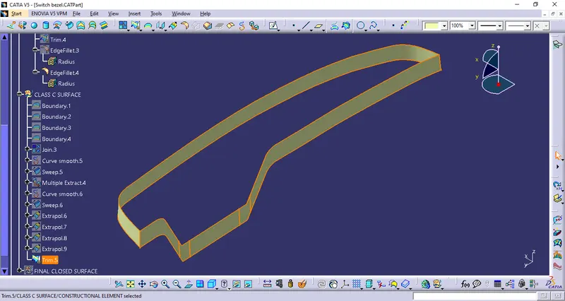
This surface is made by extracing the boundry of the class A surface and then making a sweep from the boundry with 3 degree outward along the tooling axis.
Some minor adjustments are made to make a closed surface
Class A - Yellow
Class B - Green
Class C - Blue
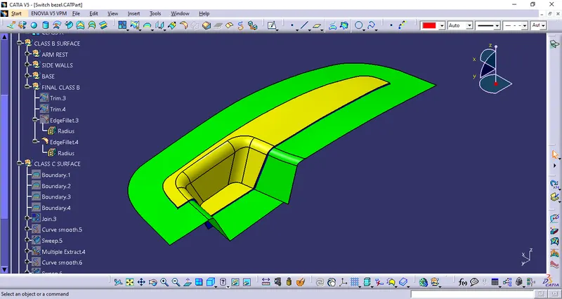
Making the final solid part:
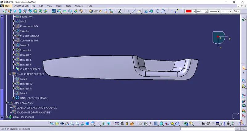
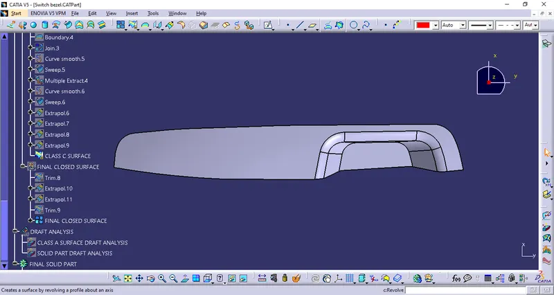
The final closed surface:
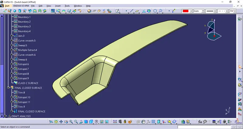
Solid surface is made by going to part work bench and the using the closed solid command on the above closed surface.
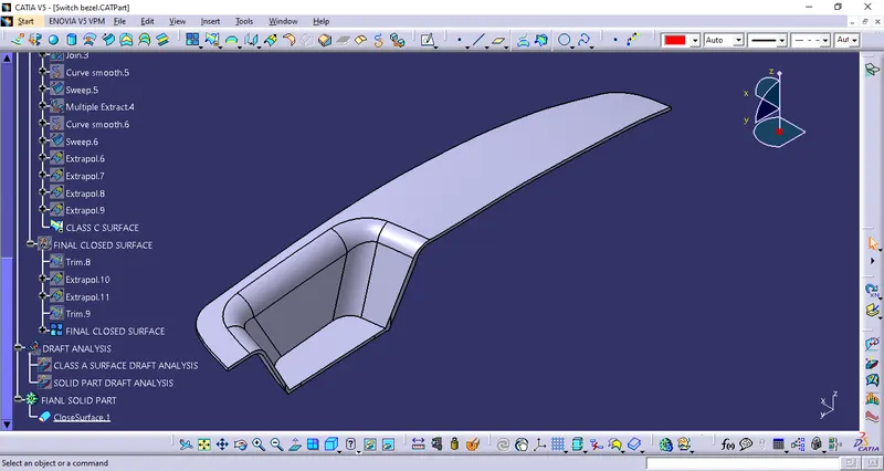
Draft analysis of the solid surface:
By using the already created tooling axis the draft analysis is done on the solid part, by using the same steps:
The inner cavity of the switch bezel is found to have the positive draft. The outer boundry of the bezel has
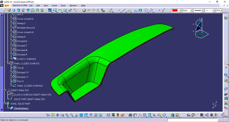
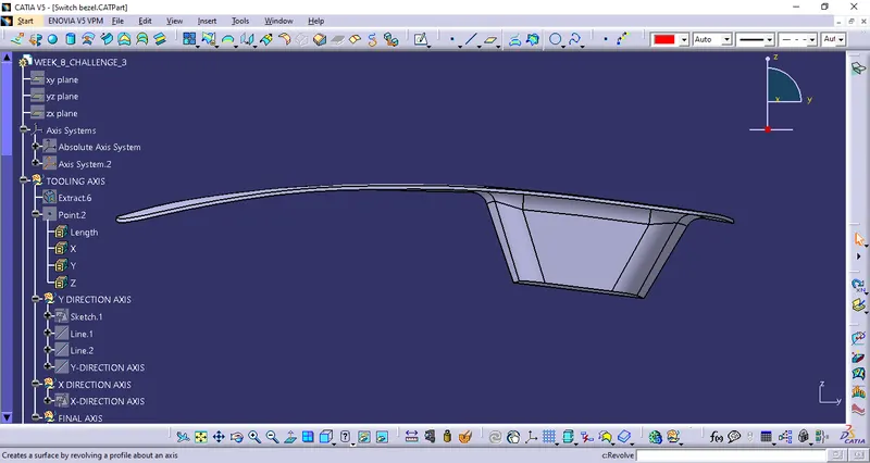
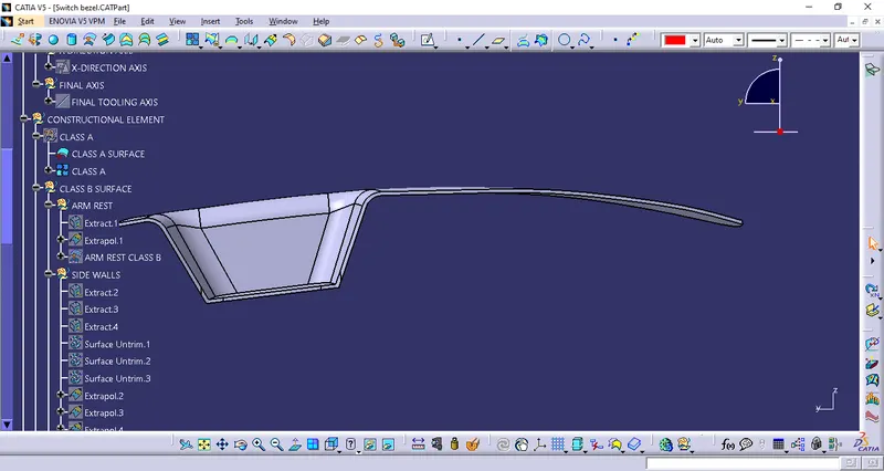
Expanded feature tree and images:
Side view:
2. Front View:
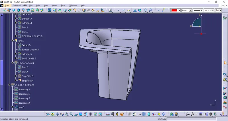
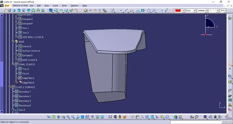
Top View:
Conclusion:
The switch bexel is designed and draft analysis is performed