Week 8 - Challenge 3 - Switch Bezel Design
AIM
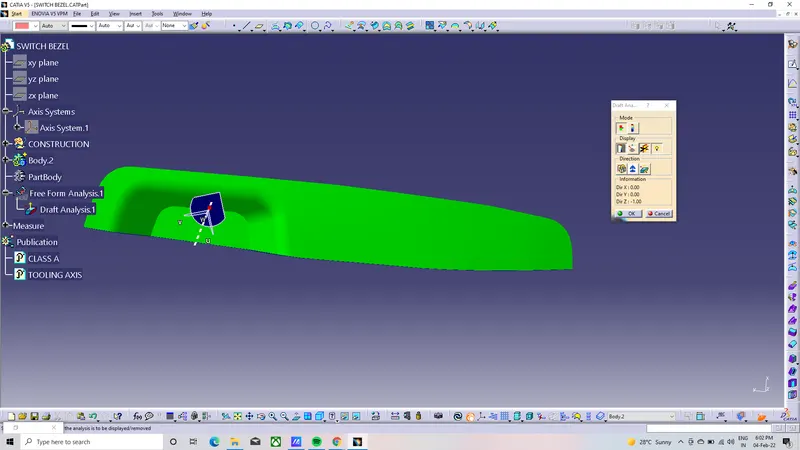
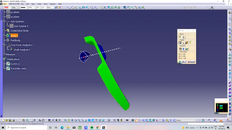
To determine the Switch Bezel Plastic component through the given Class-A surface. To begin with, the tooling axis for the given Class-A Surface should be created meeting the requirements of the draft angle and at the end perform the Draft analysis on the model.
PROCEDURE:
To create the tooling axis for the component of switch bezel
to create the tooling axis first extract the base if bezel and create the centre point.
after that keep the axis system on the centre point of the bezel base as shows in the figure
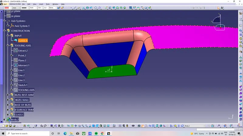
And then select the palne with bisecting tool to create the switch bezel intersecting line to create the tooling axis
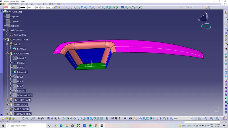
after creating the insecting of the switch bezel and create two line on the both inclined bisection line
after that extend the line and using line command create bisecting line of the tooling axis for the switch bezel
as well as shown in the figure below
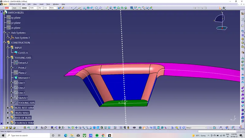
after creating the tooling axis go to CLASS A and create the extract the bezel rest arm and untrim the surface and also extracpolate and then offset into 3mm below t
and then also extract the wall of switch bezel and also extract the base of bezel and follow the step as well as same instruction should followed by bezel arm rest procedure and aslo shows the figure below
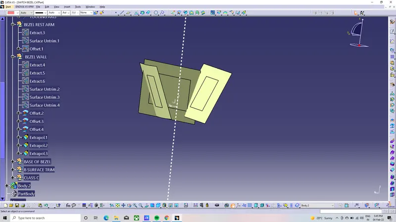
before trim
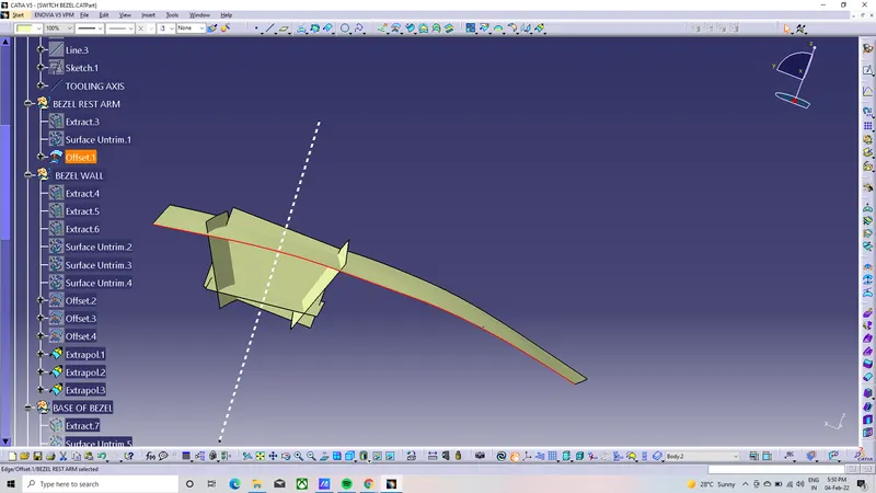
after tr im of class b surface
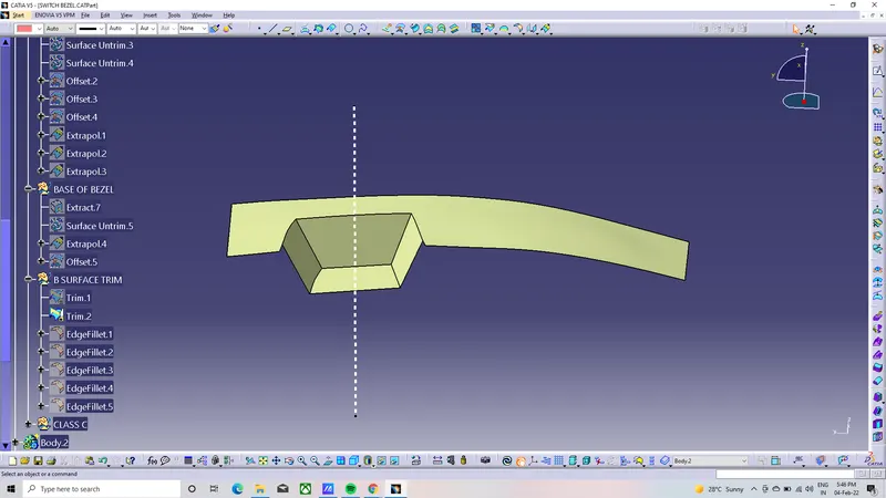
after finish the class b surface after start with the class c surface
the class c surface start with CLASS A surface with create the outer boundary of the class a surface and
and use the sweep tool and create the sweep eith 3 degree drafe and referance with tooling axis
creating sweep for class a surface
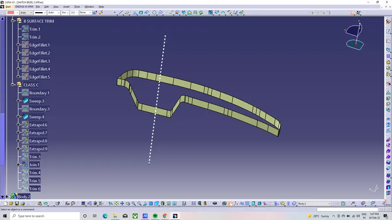
and join the sweep and CLASS A surface and class b surface
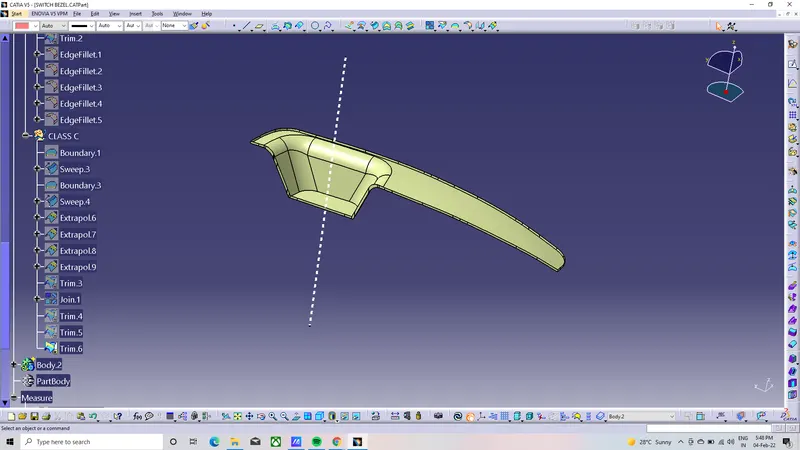
after creating the class c surface and also creted the plastic component in to solid component
in part design by using colse surface tool
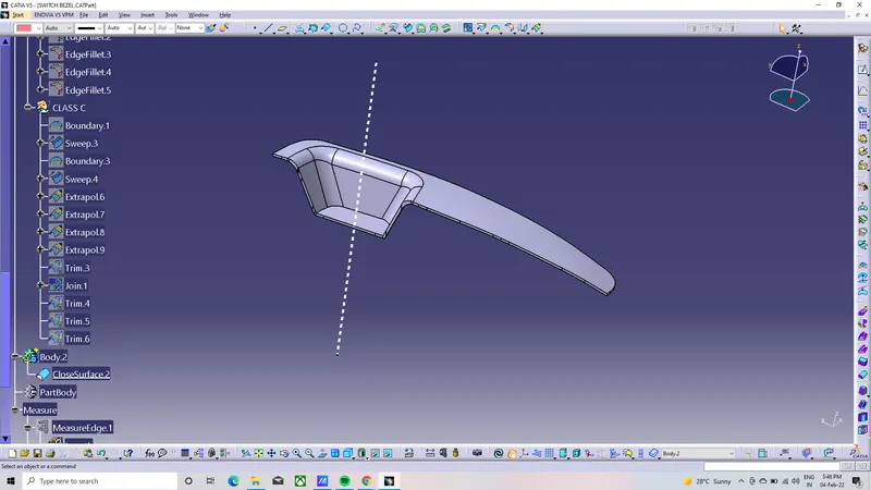
draft analysis