Week 8 - Challenge 3 - Switch Bezel Design
HELLO SIR,
Week 8 - Challenge 3 - Switch Bezel Design
OBJECTIVE:-
Create the Switch Bezel Plastic component through the given Class-A surface. To begin with, the tooling axis for the given Class-A Surface should be created meeting the requirements of the draft angle and at the end perform the Draft analysis on the model.
Take the Thickness of the component to be 2.5 mm
First, I check the connectivity of the (Class A) Switch Bezel model. Click on the join command & boundary command to check, and to ensure that there is no gap between the surfaces.
After that,
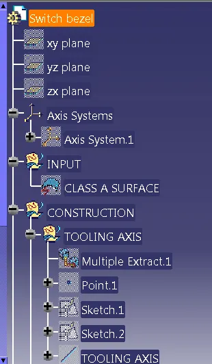
Creation of Tooling Axis
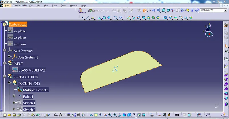
First of all, click the multiple Extract command to extract the base of the CLASS A surface, then create a point using the point command, and then create an axis system into the point.
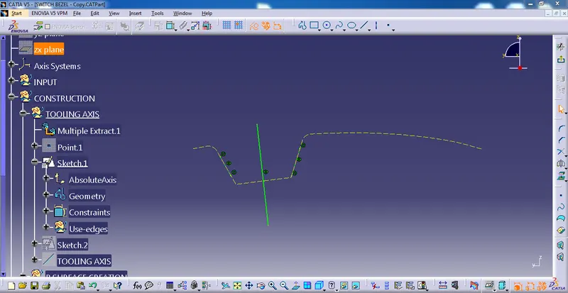
After that, create a sketch 1 on the y-z plane then bisect the two-line.
Again, create a sketch 2 on the z-x plane then bisect the two-line.
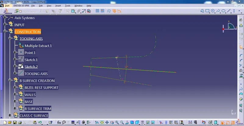
After bisecting Sketch 1 and Sketch 2 we get a Tooling Axis
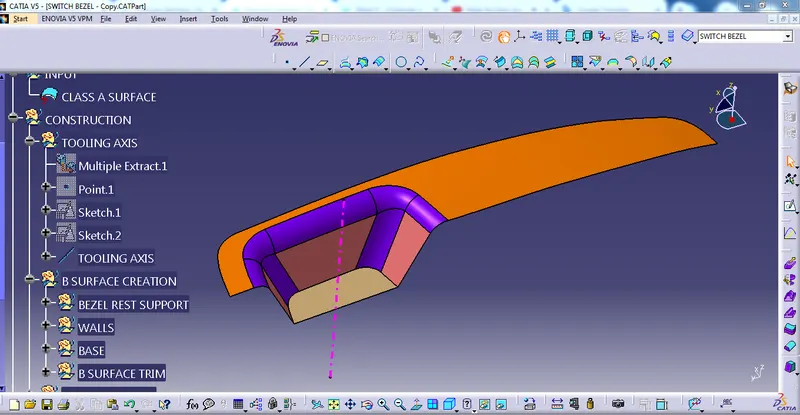
then I Published TOOLING AXIS and CLASS A SURFACE
B CLASS SURFACE CREATION
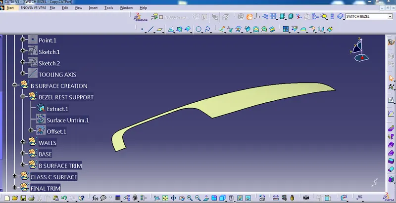
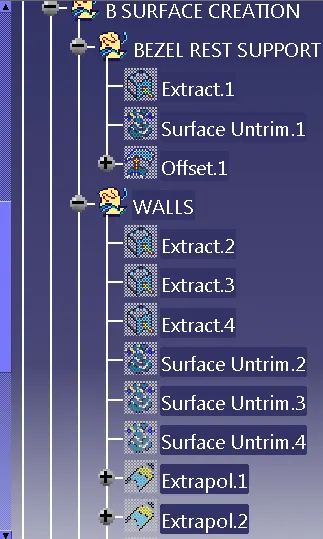
Select the top surface of the class A surface and go to the extract command to extract then go to untrim command to untrim the surface then offset 2.5 mm.
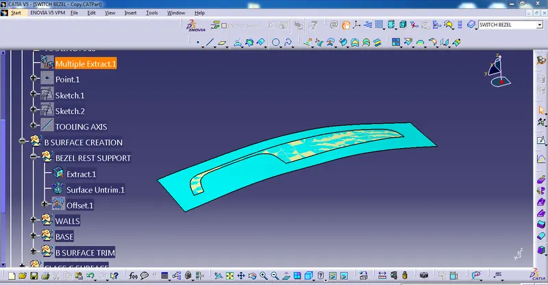
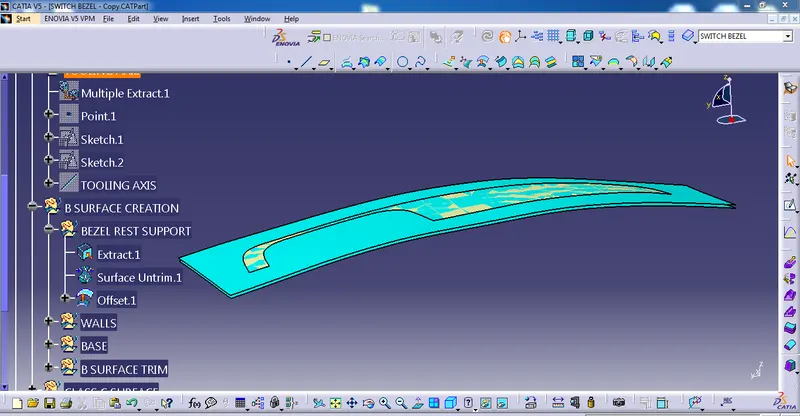
Again, Select the walls of the class A surface and go to the extract command to extract
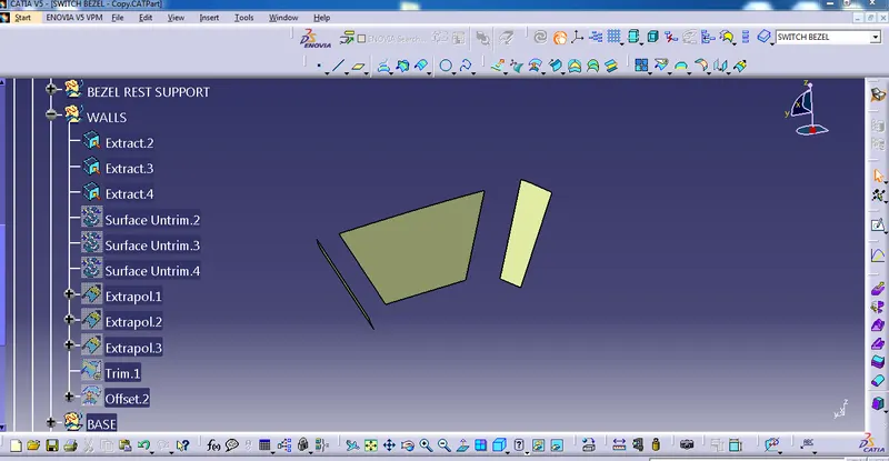
then untrim the walls
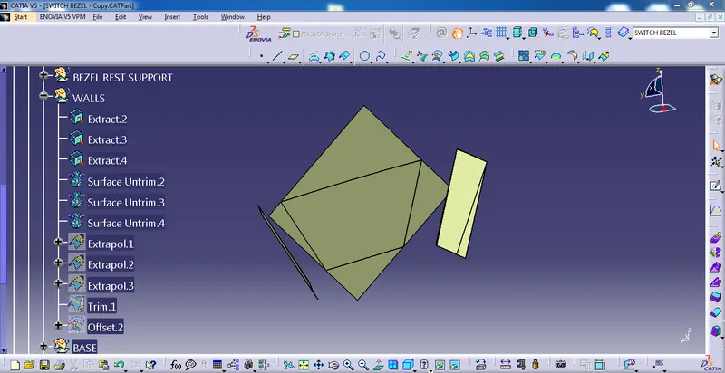
using the extrapolate command to extend the surface
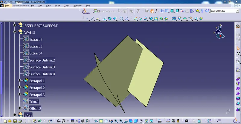
then trim the surface
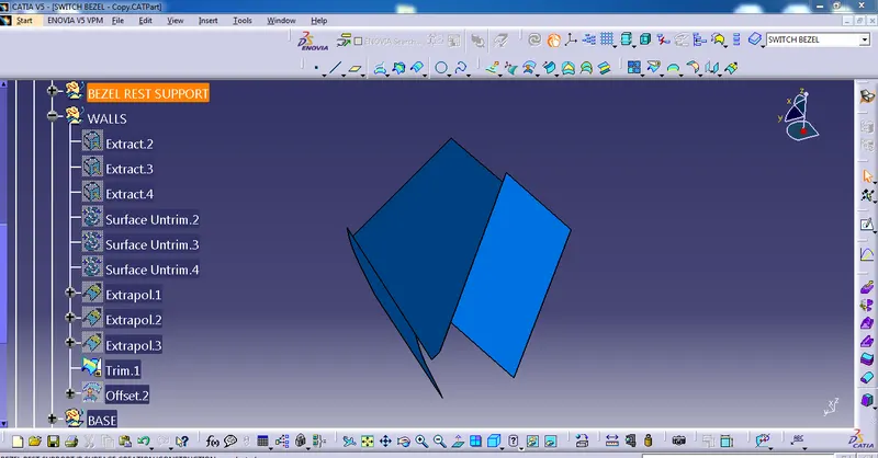
then offset 2.5 mm
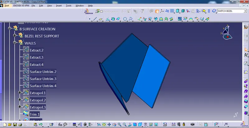
using the same procedure we have extracted, untrim, extrapolate, and offset the base of the class A surface
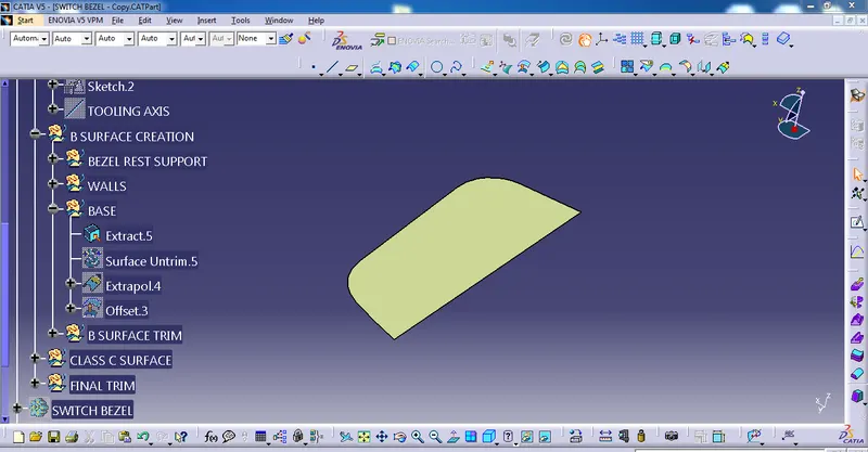
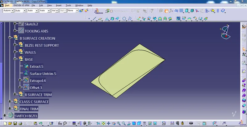
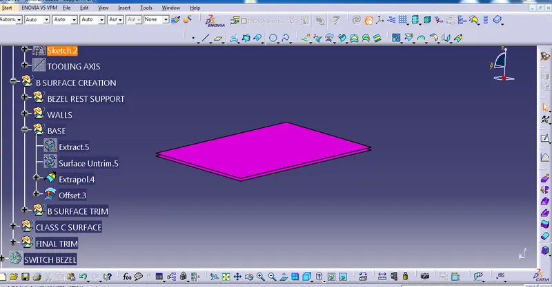
After that trim the top surface and walls
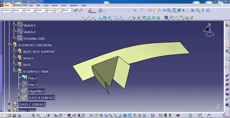
After that, trim the bezel rest wall & base surface
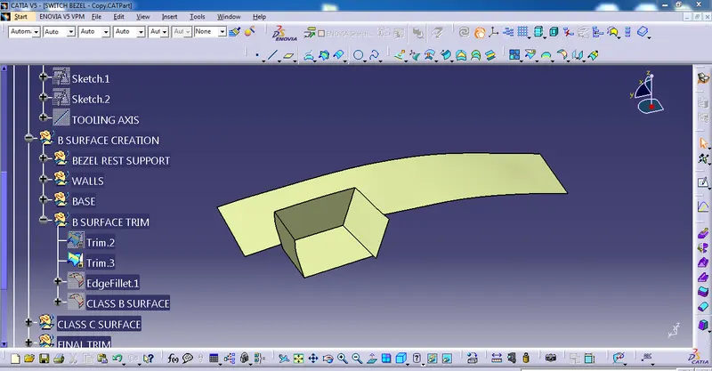
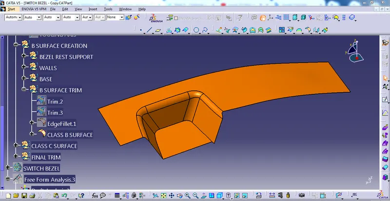
after that, go to fillet command to fillet the edge of the surface, and then, we got B class surface and then I Published.
B CLASS SURFACE
C CLASS SURFACE CREATION
Select the CLASS A surface and then go to the multiple extract command to extract the boundary.
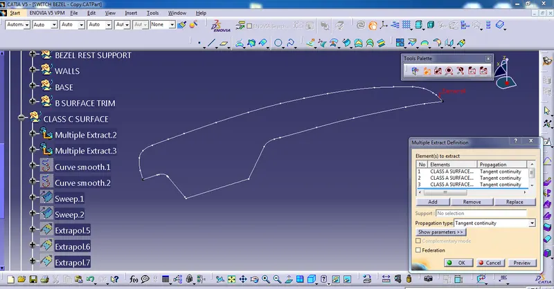
the curve is not smooth then go to the smooth curve command to smooth the curve.
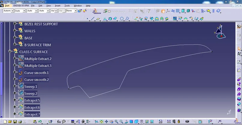
After that go to sweep command to sweep
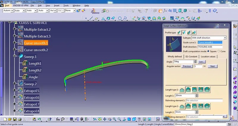
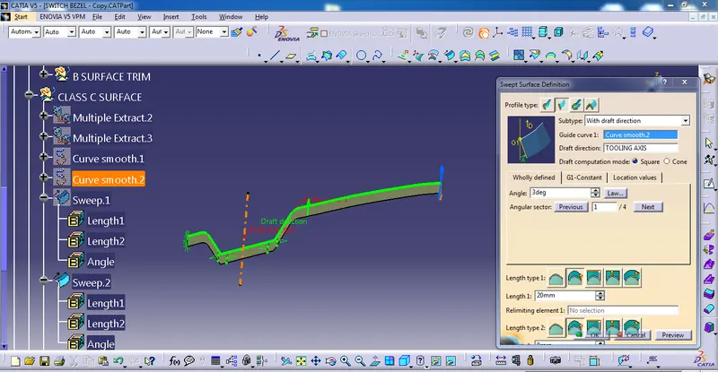
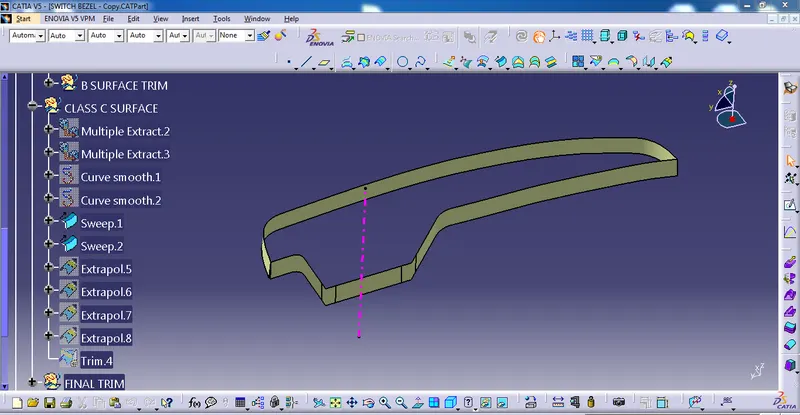
the edges are not intersected then go to extrapolate command to increase the edges
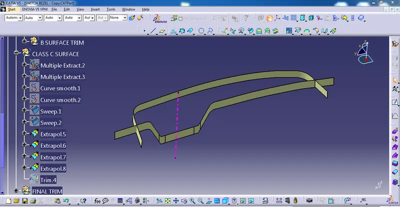
After trim
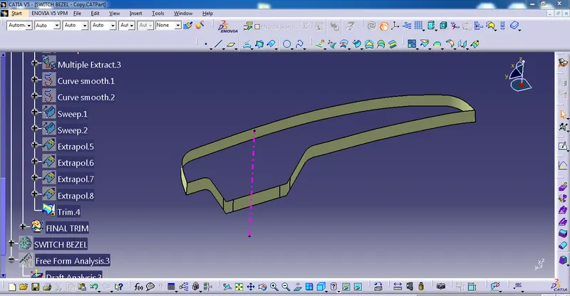
After that join the CLASS A SURFACE AND CLASS C SURFACE
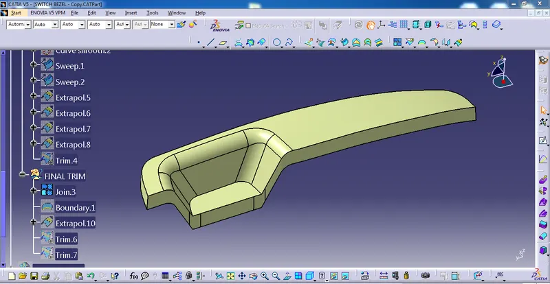
In this case, the edges are not properly closed then select the class A surface, go to extrapolated command to extand then trim the class c and extrapolate surface.
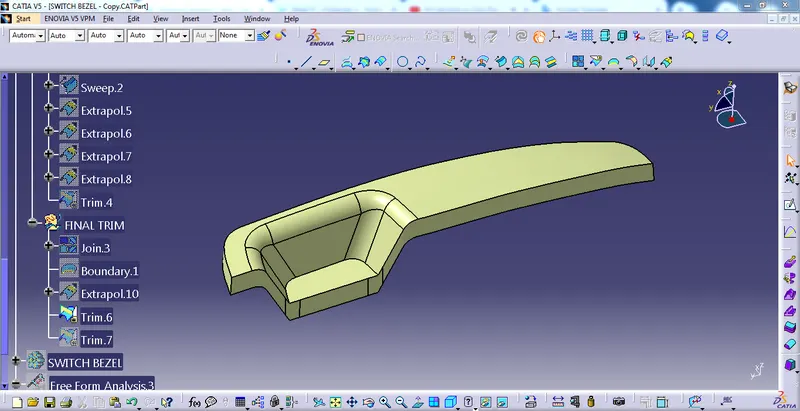
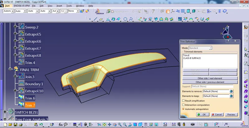
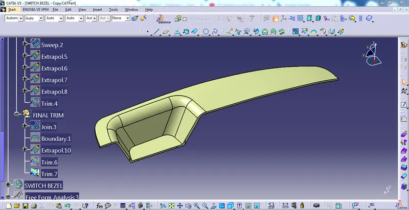
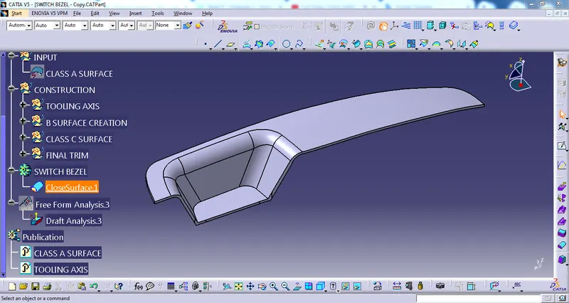
then, solidifying the component
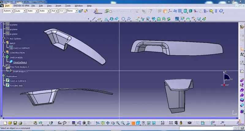
TOP, FRONT, SIDE, AND ISOMETRIC VIEW
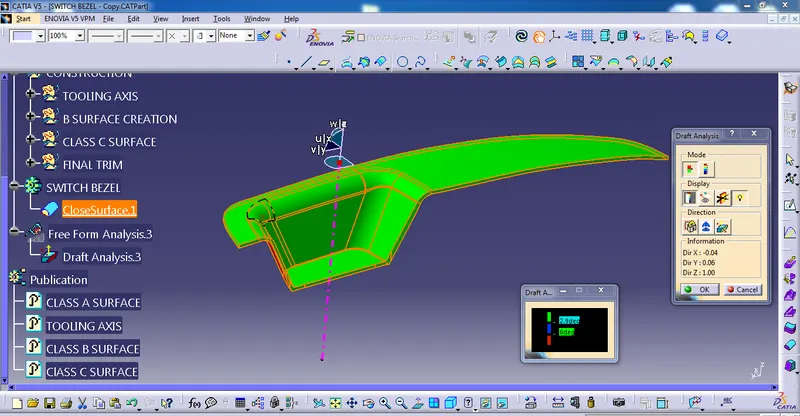
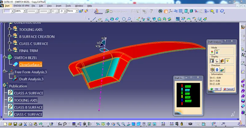
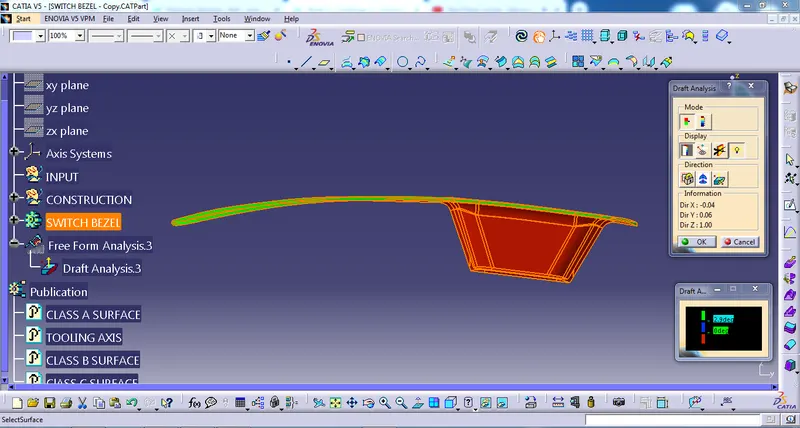
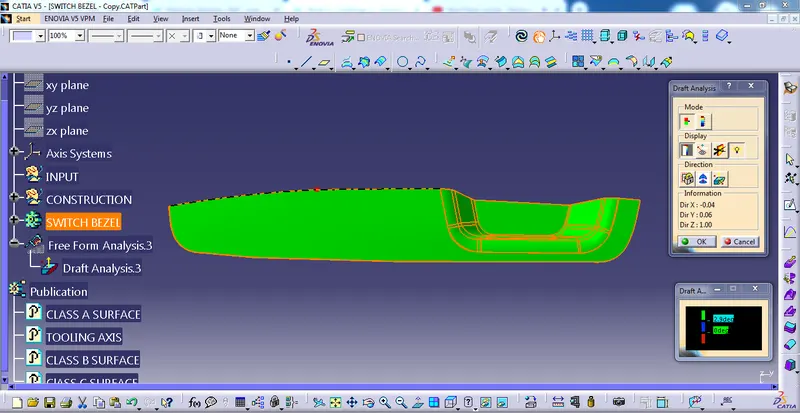
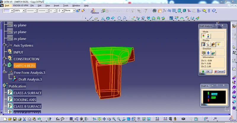
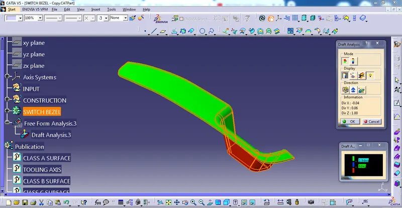
DRAFT ANALYSIS OF SWITCH BEZEL
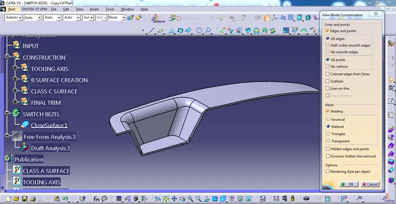
First, we have to customize the view parameter, I select the materials option, and go to the draft analysis command it will appear on the screen.
QUICK ANALYSIS MODE
FULL ANALYSIS MODE
TOP, FRONT, SIDE, AND ISOMETRIC VIEW OF SWITCH BEZEL
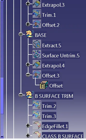
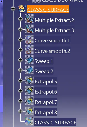
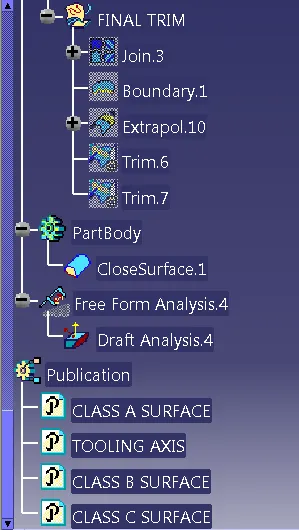
TREE STRUCTURE OF SWITCH BEZEL
THANKS