Week 8 - Challenge 3 - Switch Bezel Design
Aim:To Create a Switch Bezel Design Using OEM Standards
Objectives:
1.Creation of Tooling Axis and Draft analysis
2.Creation of class B surface
3.Creation of Class C surface
4.Ceation of Closed surface and Solid
Design Procedure :
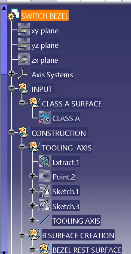
1.Creation of Tooling Axis
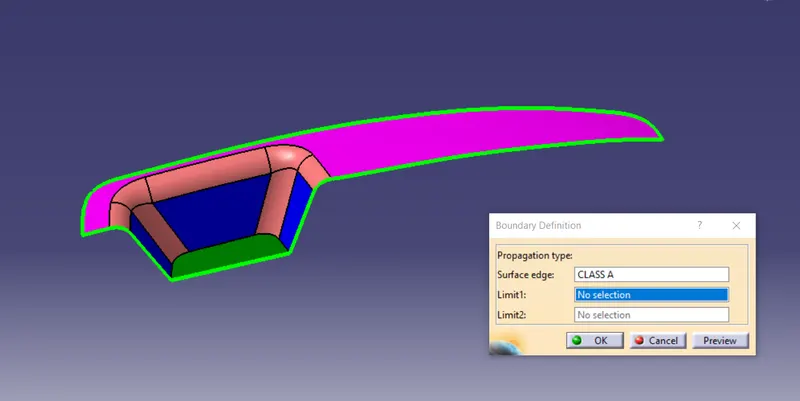
Check the connectivity of class A surface using Boudary tool or Jion tool
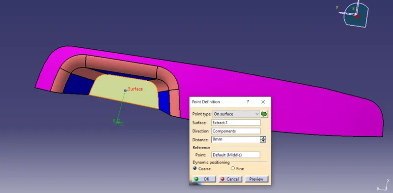
A referance point is created on surface at zero and Axis system as shown below
create a dummy toling axis
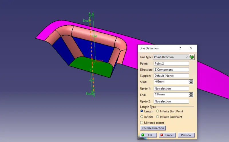
Create a Intersection from calss A surface and create a line as shown below
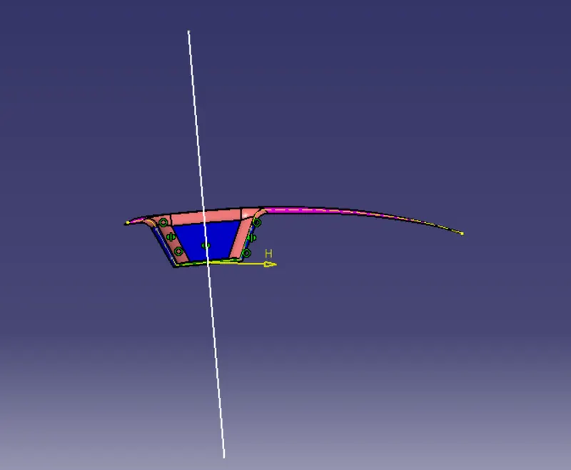
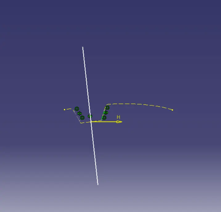
Create one more line in Y direction as shown below
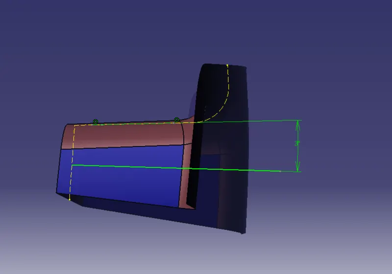
Bisect these two lines to get a tooling axis
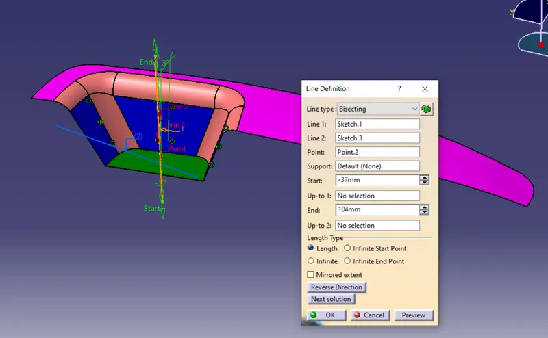
2.Creation of class B surface
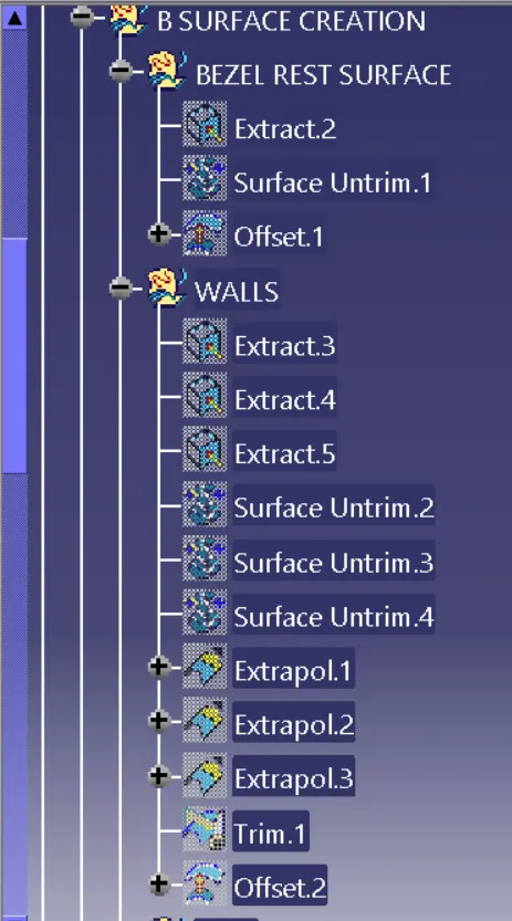
Extract the surface form class A as shown below
Untrim surface and extrapolate the surface and offset it by2.5mm
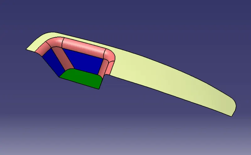
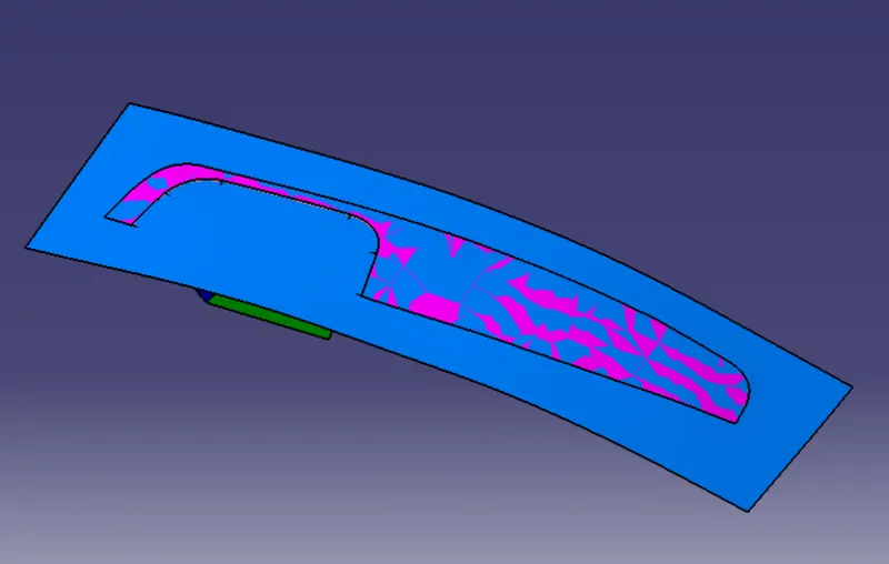
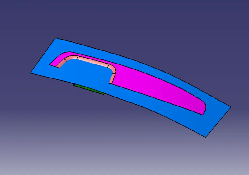
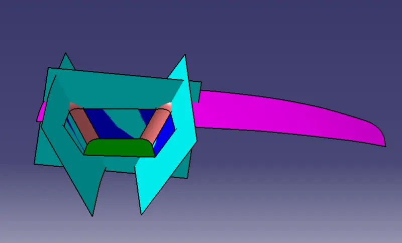
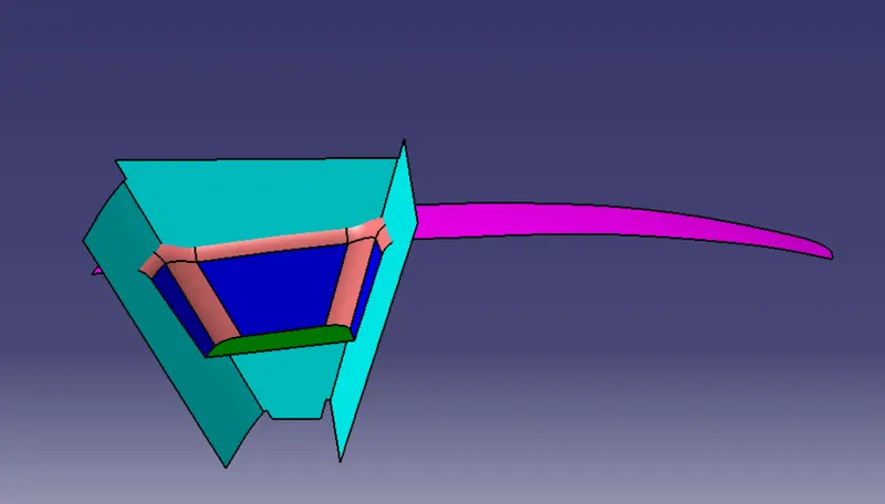
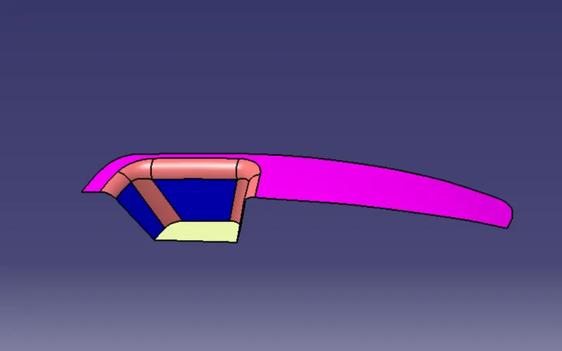
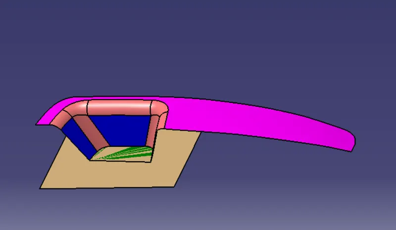
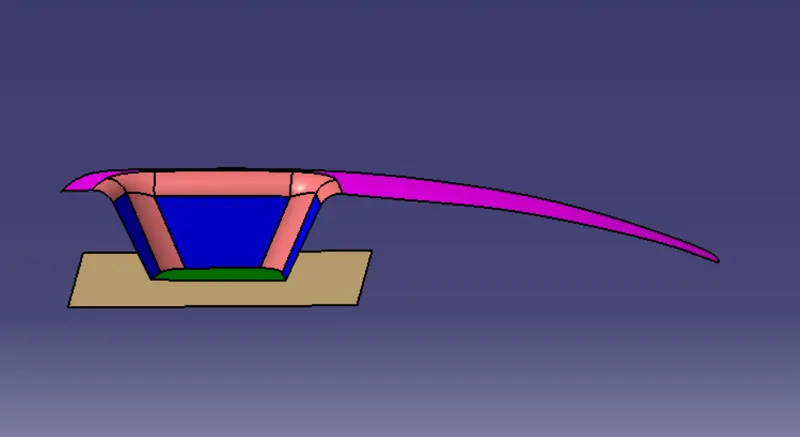
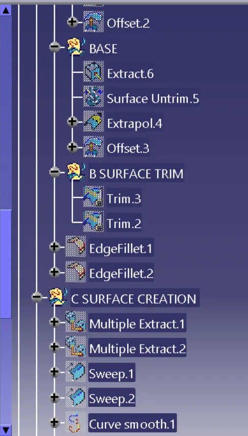
Finally trim the unncessary surfaces and fillet the edges
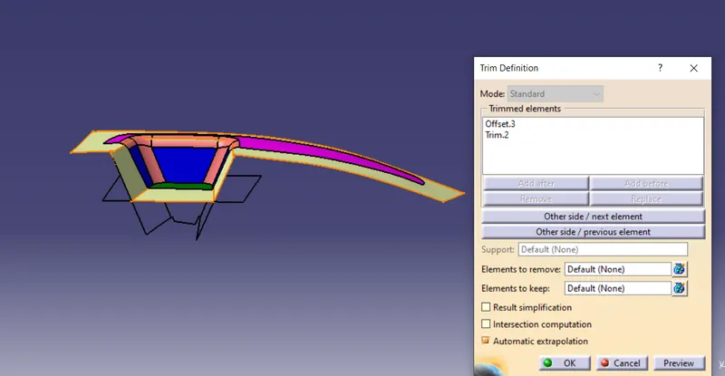
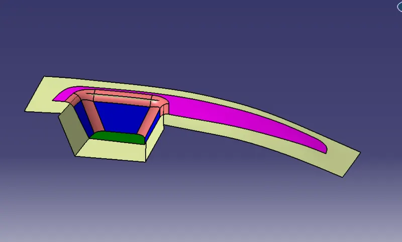
Class B surface
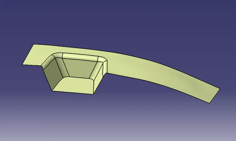
3.Creation of Class C surface
Class C surface is the joining surface between class A and class B surface.To create this surface we need to create boundary on class A and sweep it by smoothening the curve along with Tooling direction .
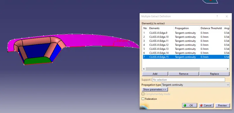
Sweep the Extracted curves along tooling axis
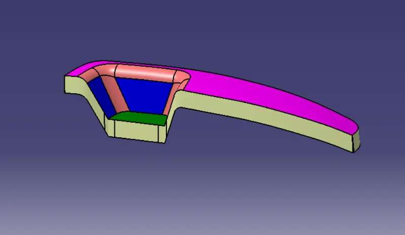
Jion the class A and class c surface using jion command and trim the unnecessary surfaces
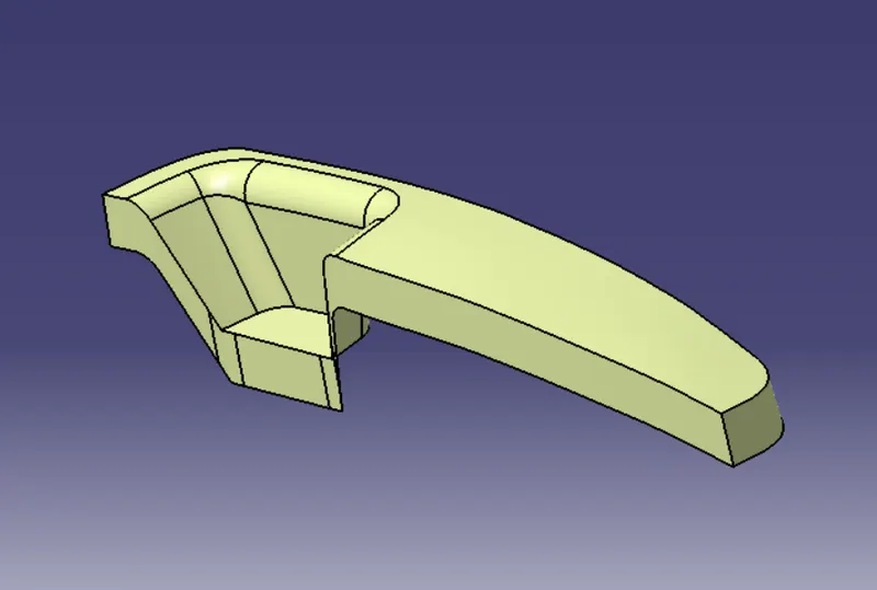
4.Ceation of Closed surface and Solid
After trimming you will get the closed surface from the closed surface create a Solid part
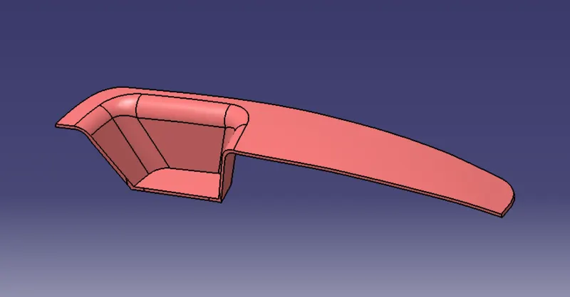
CLosed body
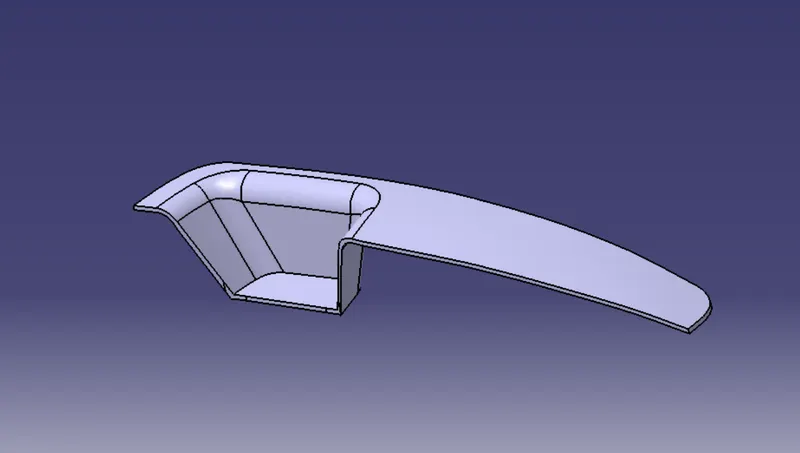
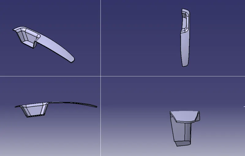
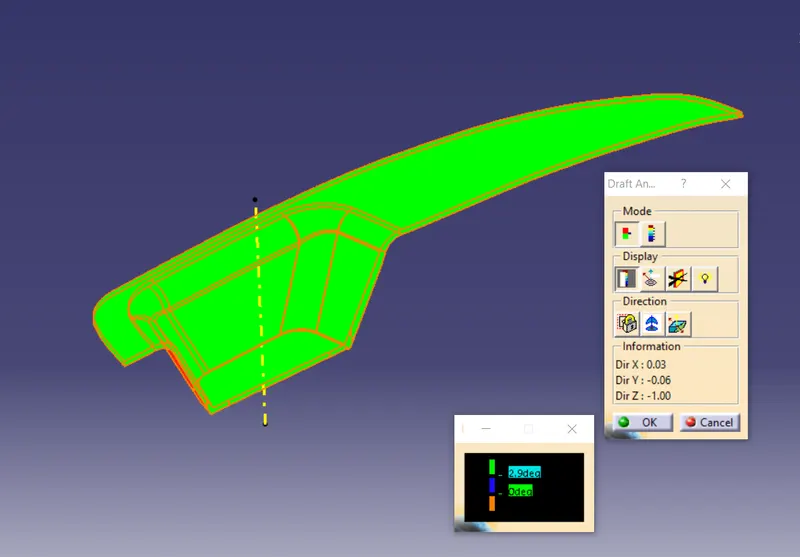
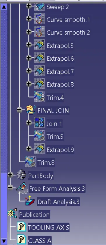
Drfat analysis
Perform a draft analysis on the component and ensure that drfat angle should be 3 degree
Feature Tree
Conclusion:
Part is created using OEM standard