Week 8 - Challenge 3 - Switch Bezel Design
SWITCH BEZEL DESIGN
OBJECTIVE:
To design a switch bezel considering all plastic product design rules.
REQUIREMENTS:
To create a tooling axis for the class A surface and do a draft analysis and also to create class B&C surface and do a draft analysis on the final product.
GIVEN INPUT:
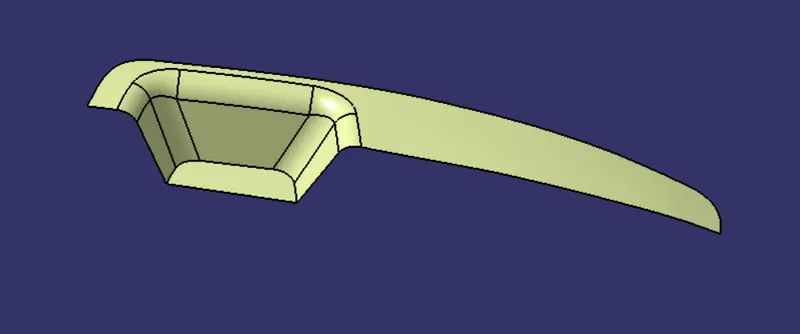
- Thickness of the component to be 2.5 mm
CREATION OF TOOLING AXIS:
The most prominent thing to be done before start designing the class B and C is to determine the tooling direction for the class A surface.
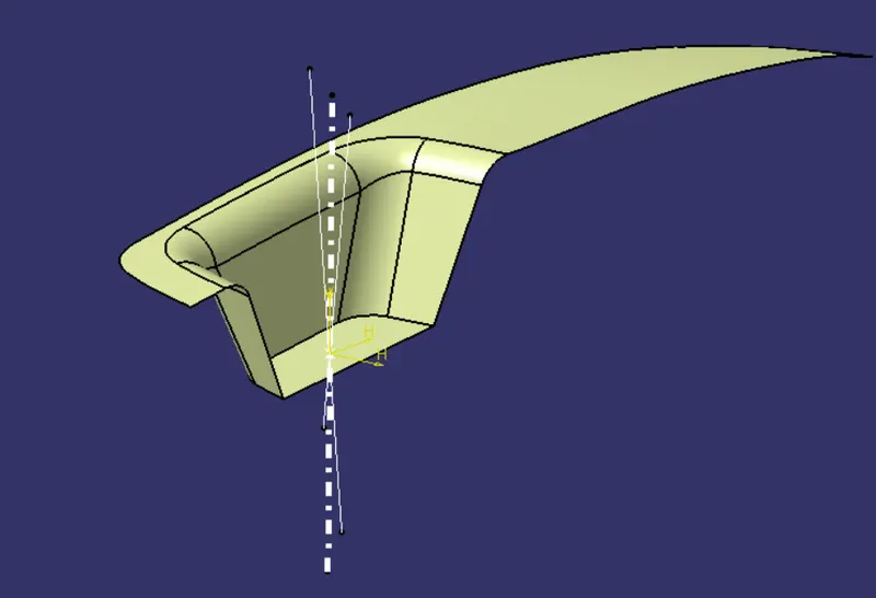
Here for this particular surface we use bisecting method to create the tooling axis
Bisecting method:
It is a method of creating the tooling axis with two reference lines. Here we have lines taken as reference from the X & Y direction.
Using intersection and taking the two side walls as reference a line is created using bisecting tool.
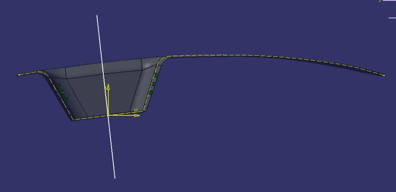
As we don't have a second wall a line is simply drawn at an angle of 7 deg tentatively to get the tooling direction as the minimum draft required for all plastic product is 3 degree.
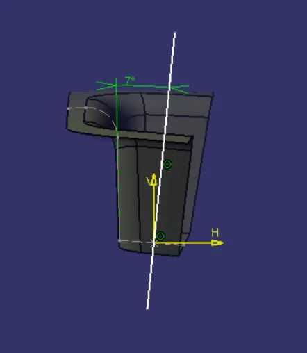
Uisng these two output lines a bisecting line is created. This bisecting line is defined as the tooling axis.
DRAFT ANALYSIS ON CLASS A:
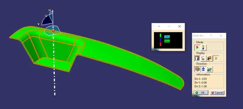
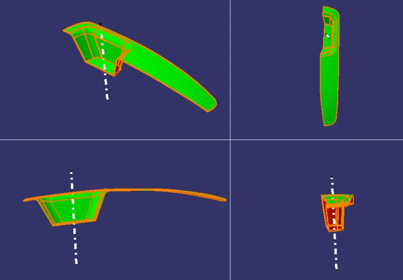
A min of 3 degree draft is required on all the faces of the surface to clear the draft analysis.
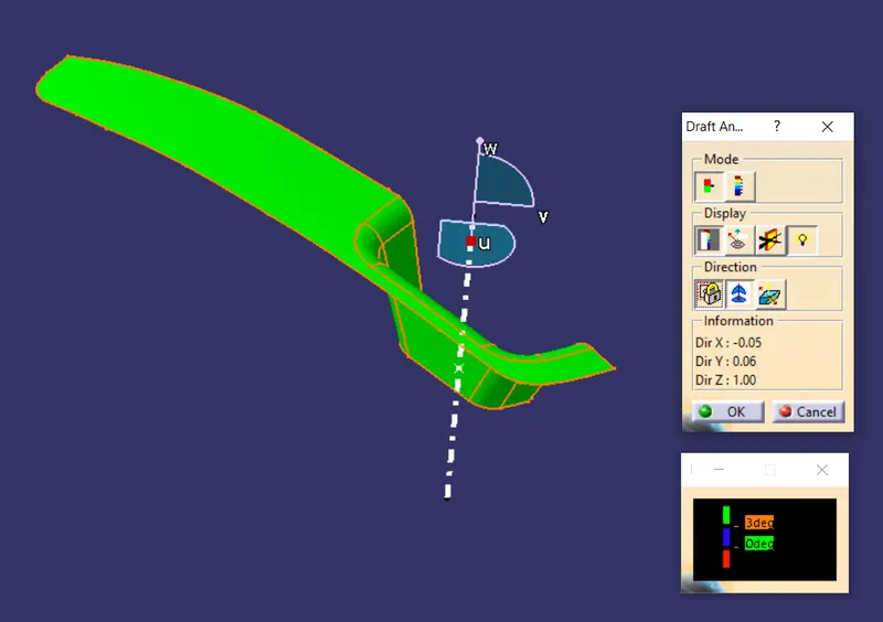
Here the colour green infers that all the faces of the surface has more than 3 degree draft.So the tooling direction which is created satisfies the draft test
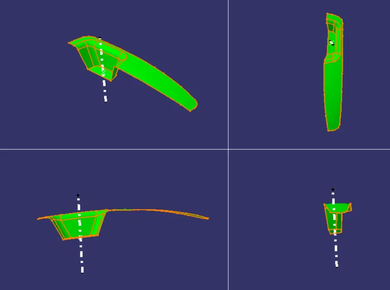
VARIOUS ORIENTATION OF THE DRAFT TEST:
CREATION OF B SURFACE:
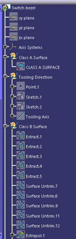
A class B surface is created taking the reference as class A. The thickness is said to be 2.5 mm so the extracted surface is extrapolated,trimmed and offsetted by 2.5mm.
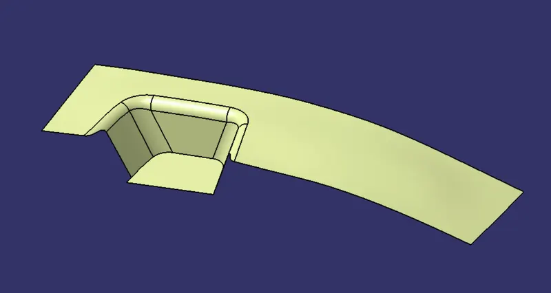
Fillet value is calculated according to which direction the surface is offsetted and given duly.It is done to avoid flash lines occuring due to varying wall thickness if we don't envisage the defect.
CREATION OF CLASS C SURFACE:
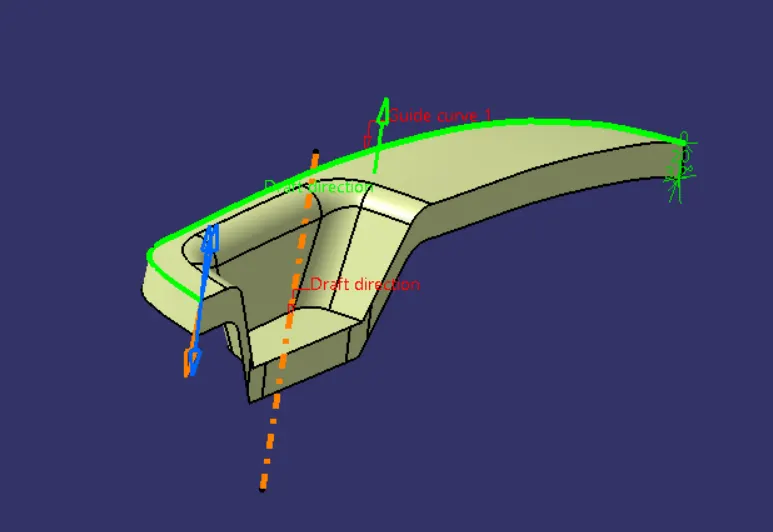
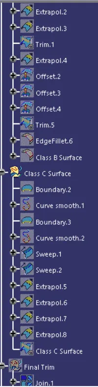
Using sweep command by taking the tooling direction as reference and the boundary as guide curve the class C surface is created.
FINAL TRIM:
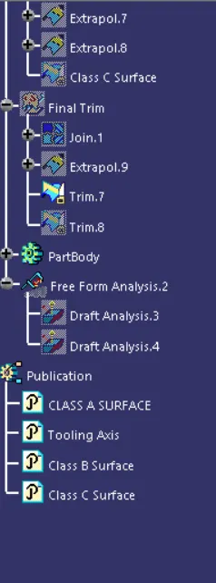
Final trim is done joining the class C and A together and trimming it along class B surface to get the desired part
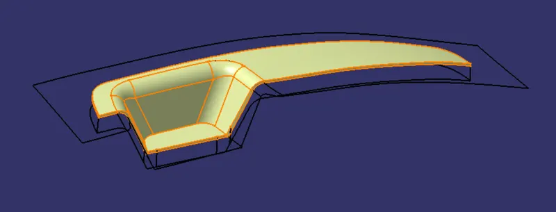
Different views of the Switch Bezel:
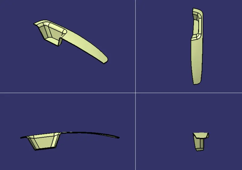
Now using the close surface a solid body is created out of the finished surface
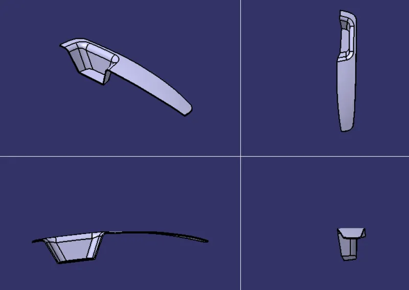
DRAFT ANALYSIS ON THE FINAL COMPONENT:
TREE STRUCTURE:
CONCLUSION:
To conclude the class B and C surface of a switch bezel is designed considering all the plastic design rules and a tooling direction is also created for the class A and also draft analysis is done on class A as well as the final component.
Software used: CATIA.