Week 8 - Challenge 3 - Switch Bezel Design
OBJECTIVE
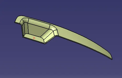
To create the Switch Bezel plastic component through the given Class-A surface and at the end performing the draft analysis on the closed surface model.
PROCEDURE
- Check the connectivity of imported of Switch Bezel model in CATIA V5 Class A Surface using boundary option. Ensure that there is no gap between the two surfaces.
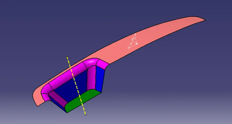
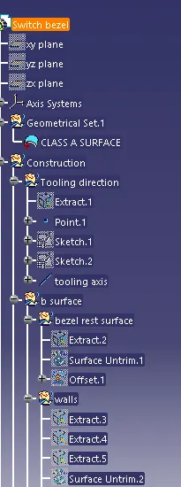
- Now we have to create the two sketches for the tooling axis for the base bracket model since it has opened end for the first sketch we have to select the two inclined edge and extract them and the bisect the line and draw another line from the middle of the surface with reference to the point and modify the angle to 6 deg of the angle. and after these two sketches done bisect the line from both the sketches the new bisected line is our tooling axis as shown below
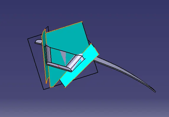
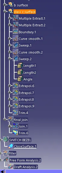
- Now we need to create a B surface which will be similar to the A surface at an offset value of 2.5 mm. In this operation we are creating a Class B surface in 3 different geometrical sets. First, we are creating a Top Rest. To create this surface, we need to extract the Class A surface as shown in below figure.
- Once the surface is extracted, untrim it and then extrapolate it by a required value on each side using point continuity. Now offset it by2.5 mm. and do the same for the remaining surfaces
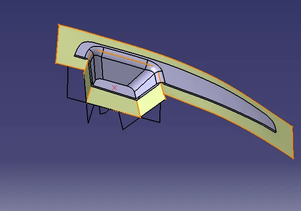
- now trim the unwanted surfaces to get the class b surface and apply the appropriate edge fillets with respect to the class a surfacenow we have o create a Class C surface, for that first extract the boundaries of the Class A surface with the help of multiple extract and then using the sweep operation sweep the extracted boundaries
- now use smooth curves to both sides reduce the edges
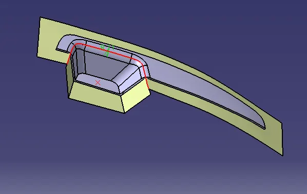
- As there are some gaps between these two surfaces, extrapolate these surfaces with appropriate value and trim them to form Class C surface as shown below
- After performing the trimming option cheak weather it has any gaps or not for that use the boundary option and click on any surface of the final trim if it shows any error then extrapolate the surface or else increse the thickness of boundaries to 0.002mm and if the boundry is not forming it means that you have good to go for closed surface
- Now jump into the part workbench with the present model and apply the closed surface operation using close surface and here we have created the closed body of our model
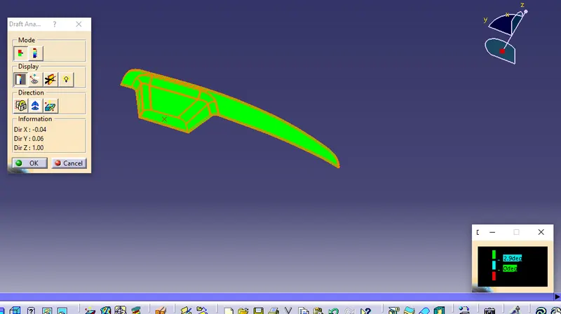
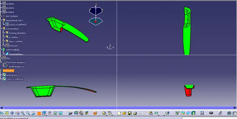
- Now we have perform drafting on this closed surface to insure that every surface is fine or not.
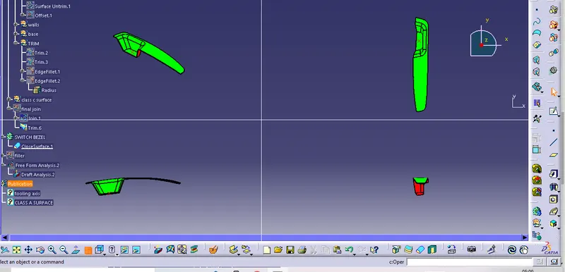
- first enable the tooling axis and drag the compass on the tooling axis and now lock the compass and click any where on the draft if the class A and class C surface shows green color it means model is passed in the drafting.
- Green color indicates that the model passed in the draft analysis also it represent the draft angle of 2.9 and above 2.9
- Blue color indicates that the model darft angle is 0 deg.
- Red color defines the negative draft angle or less than zero draft angle.