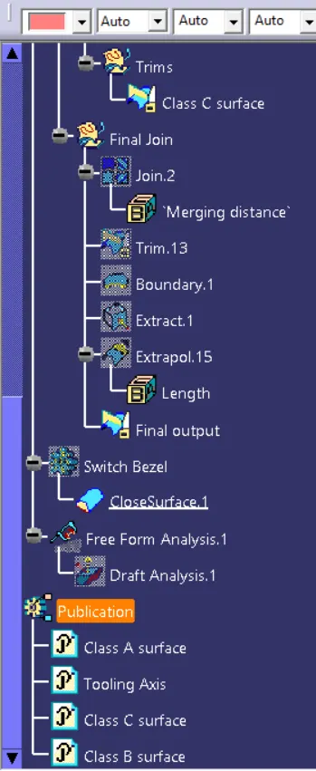
Week 8 - Challenge 3 - Switch Bezel Design
Ex-03:
Aim:
- To create a Switch Bezel using class A,B and C Surfaces.
Tools Used:
- Line
- Point
- Bisecting
- Intersection
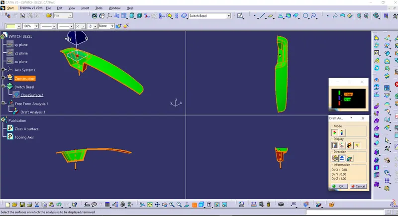
- Draft Analysis
- Extract
- Sweep
- Trim
- Extrapolate
- Edge fillets
Draft Analysis:
- Drafted parts can be easily removed from the die, for a plastic surfaces the draft angle should be @ 3deg and for a sheetmetal part the draft angle should be @ 7deg.
- This type of analysis is performed based on color ranges on the part to identifying zones.
Tooling Axis:
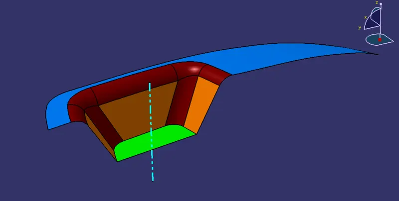
- This axis represent the tooling direction,This tooling axis can be defined by edges on the class A surface and bisecting these two lines from the class A surface gives the tooling axis.
- The below fig represent the tooling axis which is indicated in blue color.
Procedure:
- Create a point and the intersection line from the class A surface.
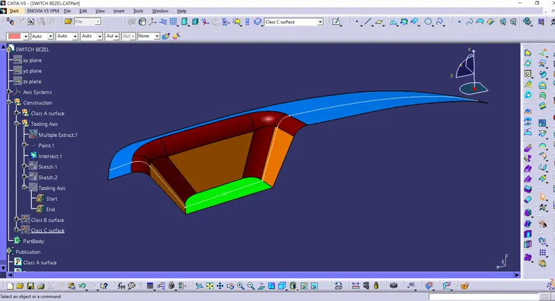
- Create a centre line from the class A surface.
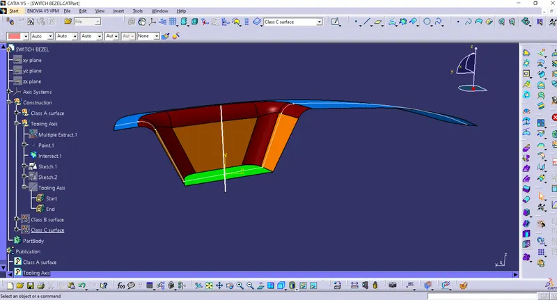
- Create another line from the right side view and intersect the line.
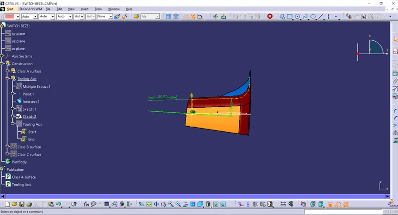
- Create a bisect line from these two lines.
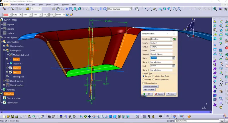
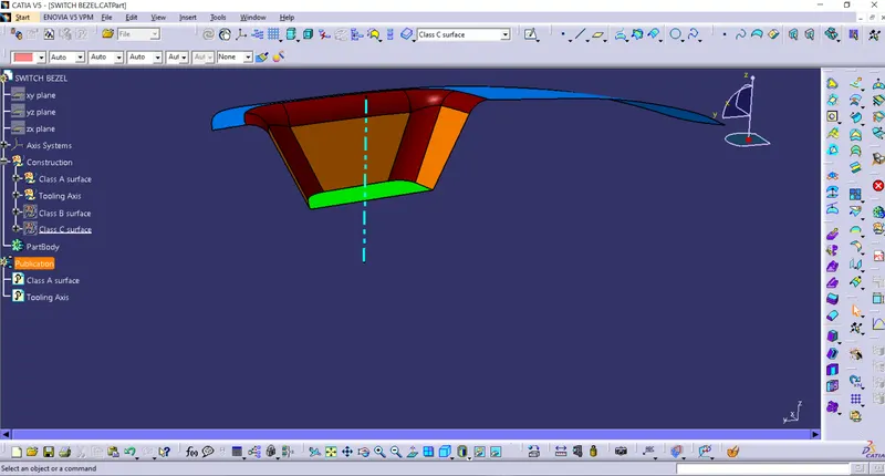
- Create an extract from the class A surface,untrim,extrapolate and offset it to 2.5mm
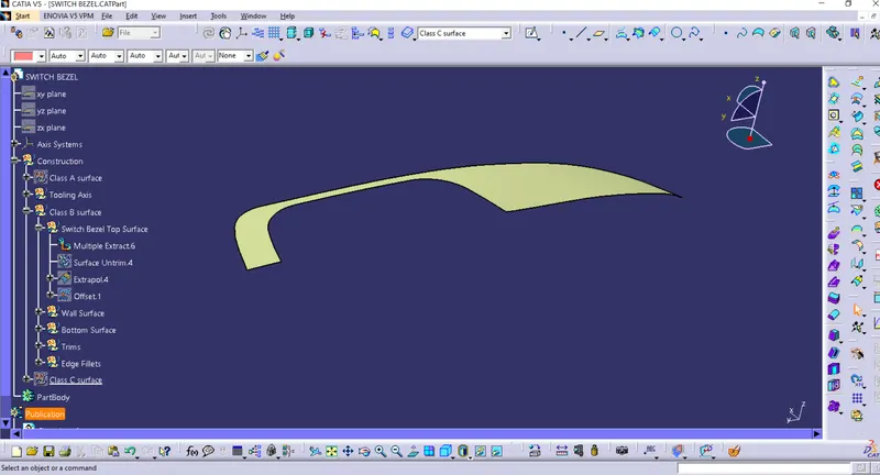
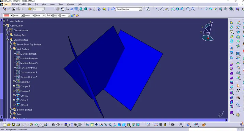
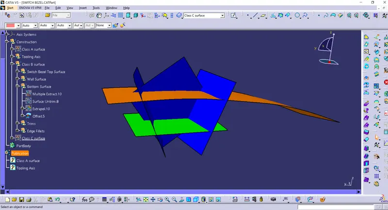
- Trim the excess portion and add edge fillet to it.
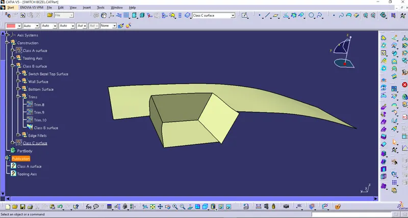
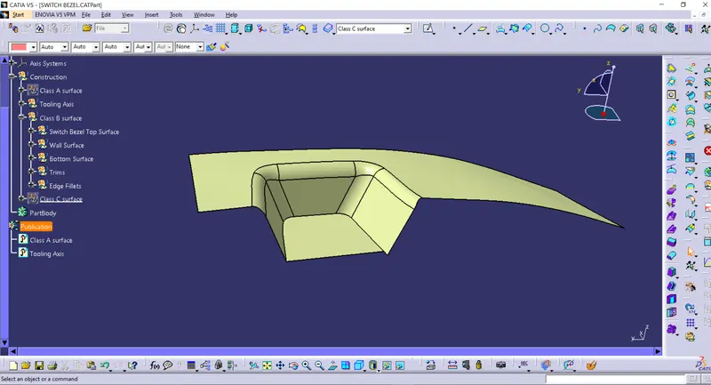
- Create Class C surface by creating boundry on the class A surface and sweep it.
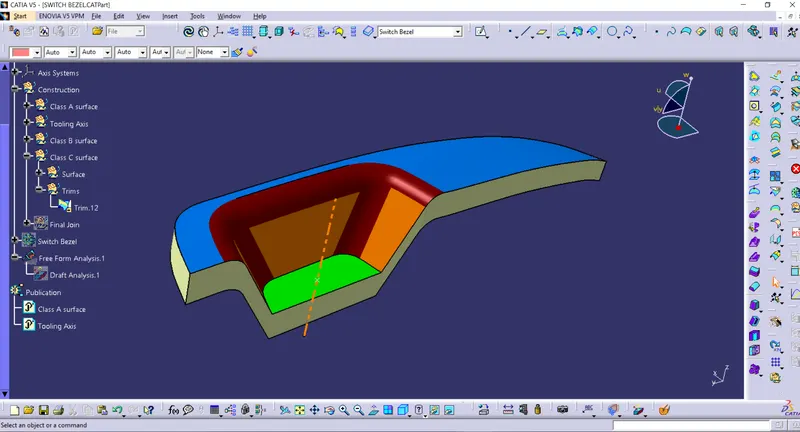
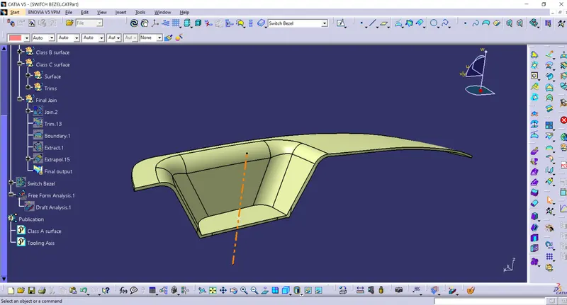
- Join the class A and C surface together and trim that surface with Class B surface and consider that all the boundries are closed.
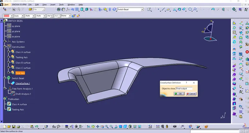
- Make the surface into solid body by using close surface tool.
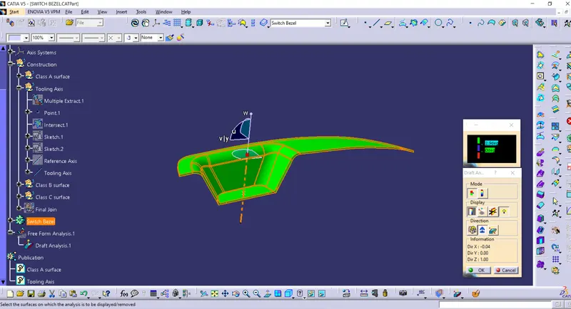
- Create an draft analysis and ensure the surface is in green color i.e the surfaces are satisfying the draft angles.
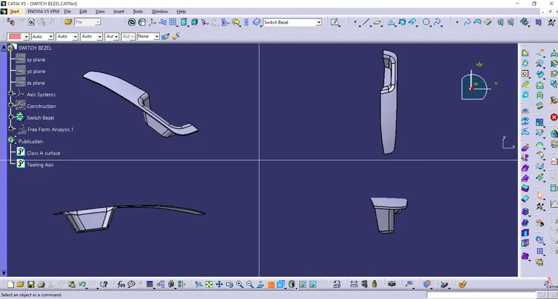
Views:(Isometric,Top,Front,Side)
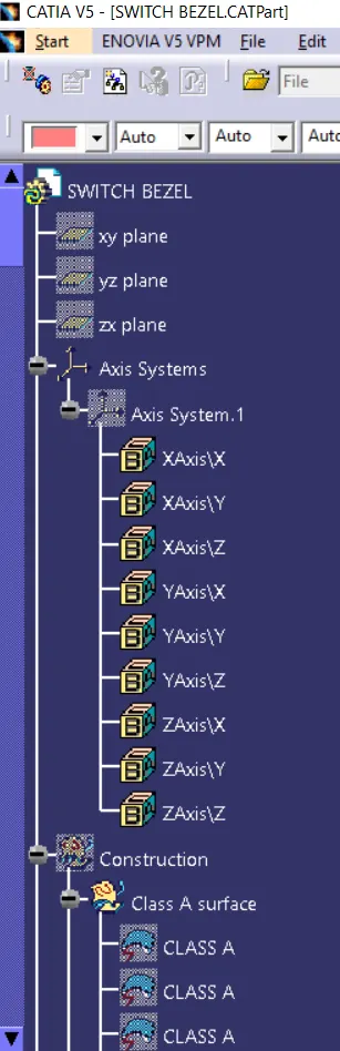
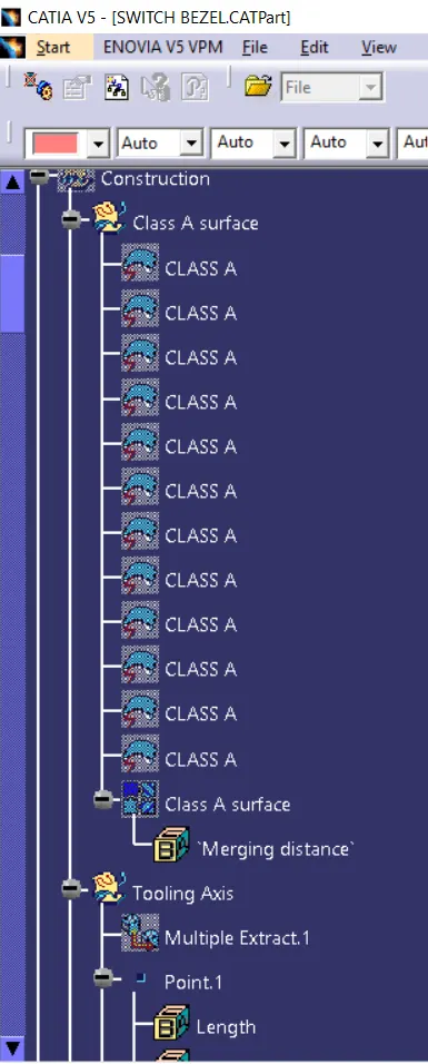
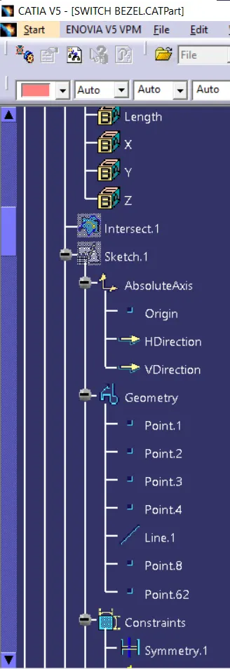
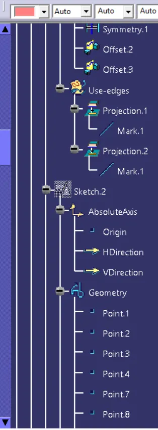
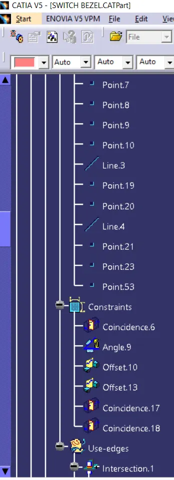
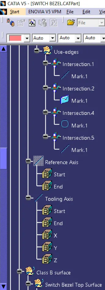
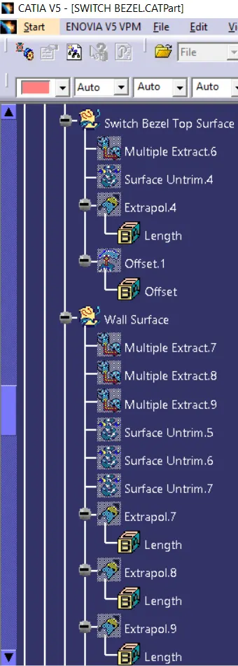
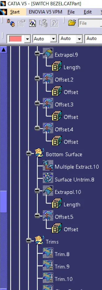
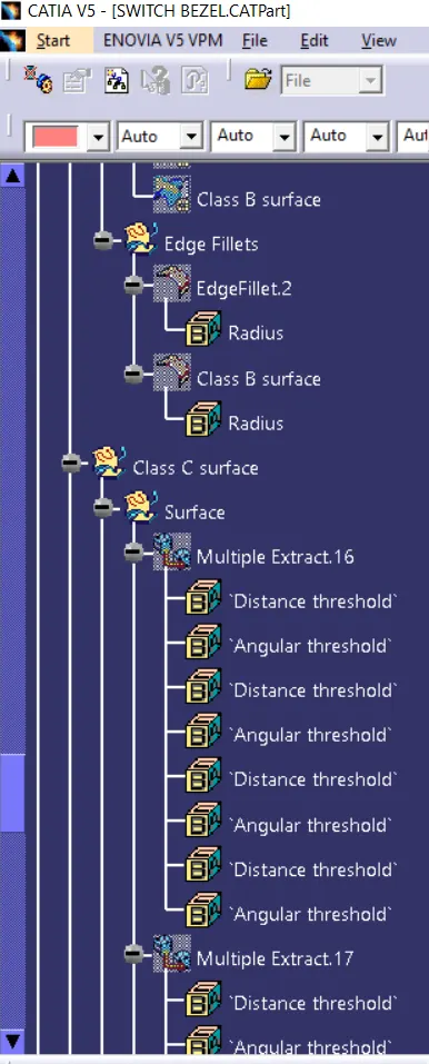
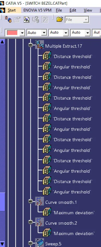
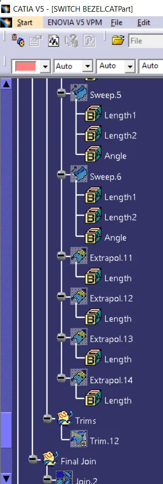
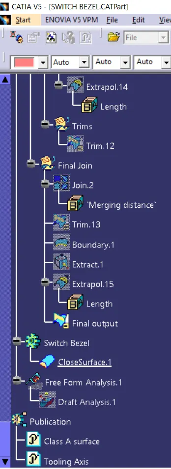
Feature Tree Manager: