Switch Bezel Design using Class A Surface
Switch Bezel Design using Class A Surface
Aim: To create the Switch Bezel Plastic component through the given Class-A surface. The tooling axis for the given Class-A Surface(shown below) should be created meeting the requirements of the draft angle and at the end perform the Draft analysis on the model.
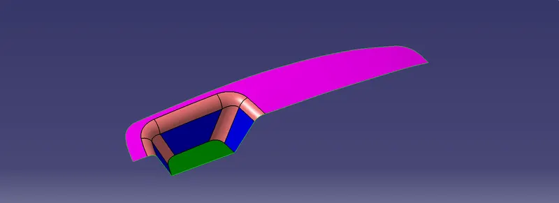
Image 1 Class A Surface
Procedure:
Following things are to be done while creating the Switch Bezel Plastic Component through the given Class A Surface.
- Creation of Tooling Axis
- Performing Drafing Analysis on the given Class A Surface with respect to the created tooling axis
- Creation of the Class B Surface
- Creation of Class C Surface
- Joining all three surface to form Closed Surface
- Performing Draft Analysis on the Closed Surface
- Creating Solid using the Closed Surface
1. Creation of Tooling Axis:
Step 1: Creating Dummy Tooling Axis
Initally a dummy tooling axis is created according to the Class A surface. Features of the Class A surface, such as Holes, Fillets, chamfers etc, is considered while creating the dummy tooling axis.
In the given model, most of the surface is flat. Hence, a dummy tooling axis is created the middle of the base surface. To create a dummy tooling axis
Create a point in middle of surface> Create an axis on that point having a plane parallel to the flat surface> Create a line point-direction- select the circle center, select z axis as direction(Refer the image below)
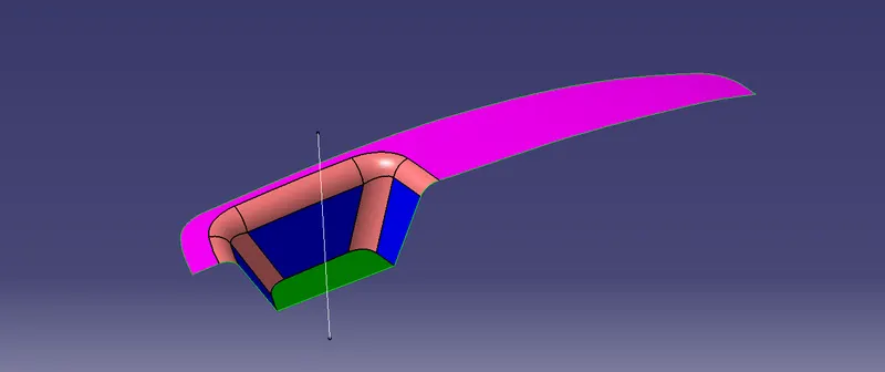
Image 1.1 Dummy Tooling Axis
Step 2: Create Tooling Axis
To create Tooling Axis for the given component
Create an Intersection curve between the yz plane and the class A surface> Create a Line using the two points of the side walls of the switch bezel on both sides> Create a new bisecting line between the two newly created lines> This will be the Tooling axis for y direction.(refer the image below)
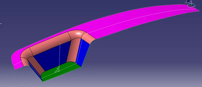
Image 1.2 Tooling Axis
Simlarly a new tooling axis is to be created in y direction. To create X tooling axis with respect to side wall of switch bezel
Create intersection curve between the xz plane and the class A surfaceCreate a Line using the two points of the side walls of the switch bezel> Create a line passing through the middle point and at an angle of 4 degree with respect to the intersection line(refer the below image)
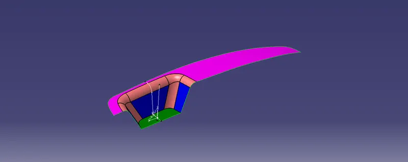
Image 1.3 X Tooling Axis
To create the tooling axis using the x and y tooling axis
Create a line using bisecting method by select the x and y tooling axis.(refer the below image)
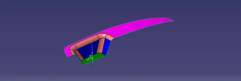
Image 1.4 Tooling Axis
2. Performing Drafing Analysis on the given Class A Surface with respect to the created tooling axis.
Drafting analysis is done on the Class A surface to verfiy whether the Tooling Axis Created is correct or not. To perform drafting analysis
Insert>Analysis>Feature Draft Analyisis> Select the Class A Surface> Set the Draft Angles> Fix the Axis on to the Tooling axis(refer the below image)
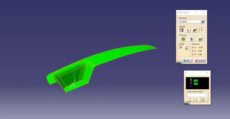
Image 2.1 Drafting analysis on Class A Surface
3. Creation of the Class B Surface
Surface Offset Method is used to create Class B Surface. In this method Flat surface on Class A is extracted and offset to specified thickness> Extrapolated in all Direction> Trimmed to get Class B Surface> Fillet is add wherever neccessary(refer the below image)
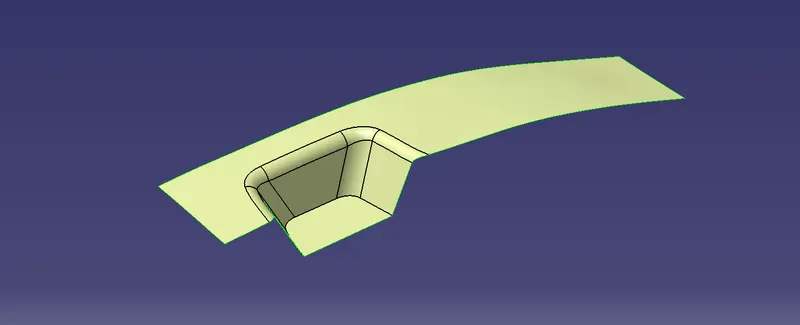
Image 3.1 Class B Surface
4. Creation of Class C Surface
To create class C surface, The boundary of Class A Surface extruded using Spline tool(Draft Direction)(refer the below image)
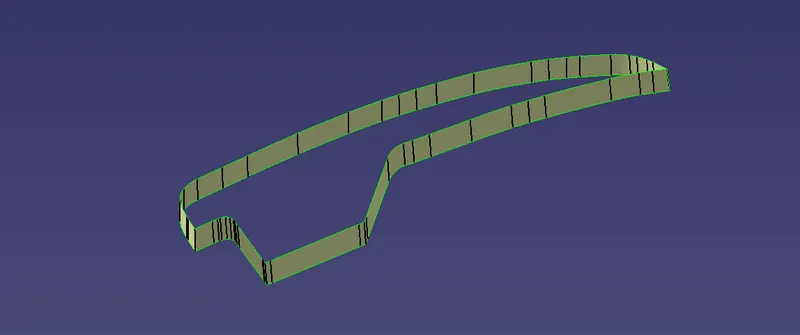
Image 4.1 Class C Surface
5. Joining all three surface to form Closed Surface
Joined Class A, Class B and Class C surface using Trim Tool.(refer the below image)
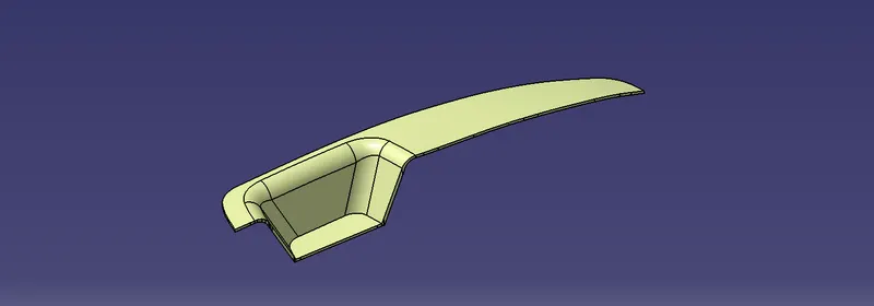
Image 5.1 Closed Surface
6. Performing Draft Analysis on the Closed Surface
Draft analysis is performed on the Closed Surface.(refer the below image)
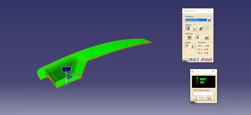
Image 6.1 Draft Analysis on the closed surface
7. Creating Solid using the Closed Surface
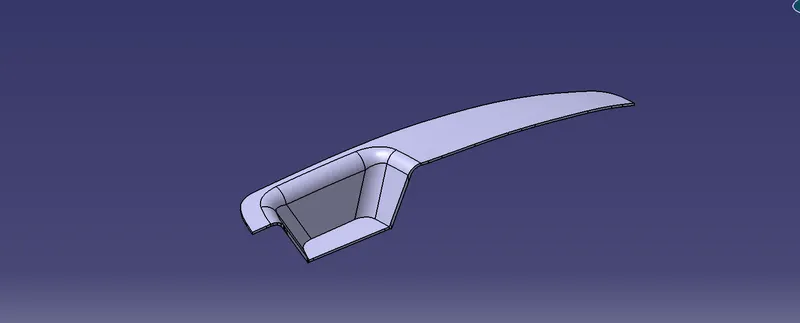
Image 7.1 Solid Creation using the Closed Surface
Complete Model:
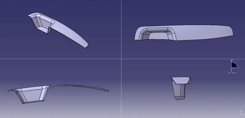
Model Tree
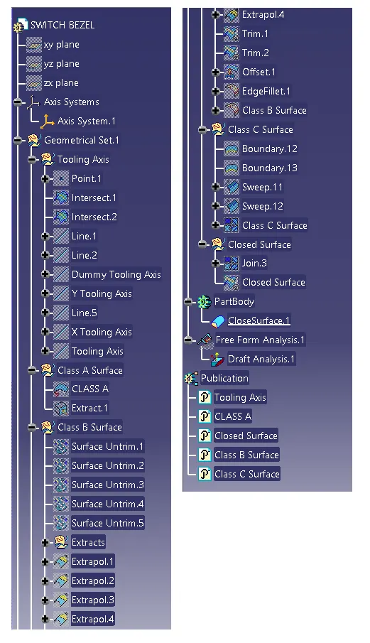
Conclusion: Performed following operation to create Switch Bezel from the given Class A Surface
- Creation of Tooling Axis
- Performing Drafing Analysis on the given Class A Surface with respect to the created tooling axis
- Creation of the Class B Surface
- Creation of Class C Surface
- Joining all three surface to form Closed Surface
- Performing Draft Analysis on the Closed Surface
- Creating Solid using the Closed Surface