Week 8 - Challenge 3 - Switch Bezel Design
Tooling axis for the given Class-A Surface:
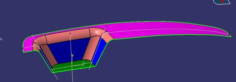
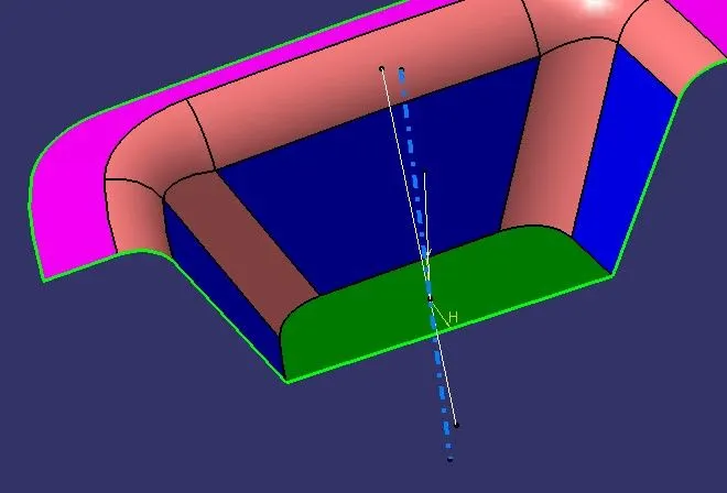
The tooling axis is an axis in which direction we can easily pull out the product from the core and cavity. It is the main axis through which a mold moves from the cavity.
Using the tooling axis created along the x and y-axis, these tooling axes are used for the creation of the tooling axis by a bisecting method where the two lines and points will be selected as inputs.
To create the tooling axis, we used initially intersect feature to create the outer boundary. Draw two lines on the faces boundary for the creation of the tooling axis. Now draw a bisecting line with the help of both inclined lines. This bisecting line is called the tooling axis.
Screenshots of the Draft analysis report for both the given Class-A surface of the Switch Bezel:
A draft is required to eject the mold from the cavity. The draft is necessary for ejection of the molded part easily. If the draft will not apply then some problems could be created in the production of models. So Draft analysis is done in designing part of the Base Bracket after completing the tooling axis creation.
Use the compass to define the new current draft direction. After that lock the draft direction.
Quick analysis mode:
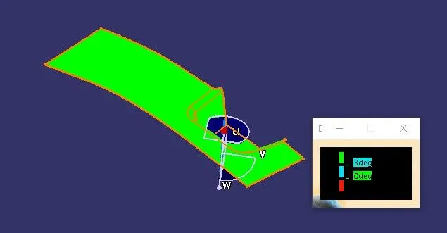
In this image, the green color shows that the minimum draft angle is 3 degrees angle and more than that.
Here on the right-side color box shows blue color at 0 to 3 degrees angle and the red color shows a negative angle. But here no red color is showing that means no face is at an o degree angle.
Full analysis mode:
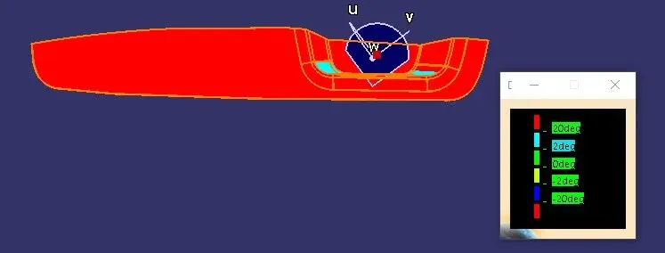
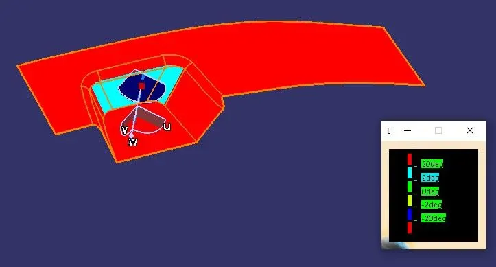
In this image red color shows that the minimum draft angle is 20 degrees angle and more than that and the light blue color shows that the draft angle is between 2 to 20 degrees angle.
Here on the right-side color box shows green color at 0 degrees angle and yellow color shows at -2 degrees angle and blue color shows -20 degrees draft angle.
Screenshots of the Draft analysis report for both the given plastic component C surface of the Switch Bezel:
Quick analysis mode:
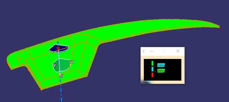
In this image, the green color shows that the minimum draft angle is 2 degrees angle and more than that.
Here on the right-side color box shows blue color at 0 to 2 degrees angle and the red color shows a negative angle. But here no red color is showing that means no face is at an o degree angle.
Full analysis mode:
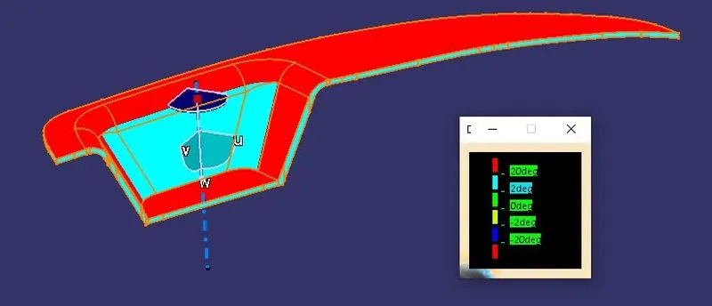
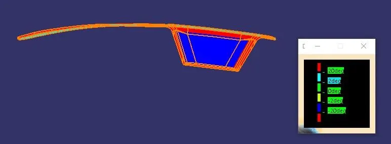
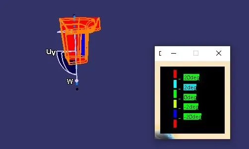
In this image red color shows that the minimum draft angle is 20 degrees angle and more than that and the light blue color shows that the draft angle is between 2 to 20 degrees angle.
Here on the right-side color box shows green color at 0 degrees angle and yellow color shows at -2 degrees angle and blue color shows -20 degrees draft angle.
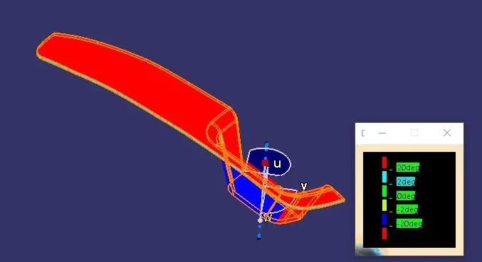
The solid model with the proper color code of the draft angle in various orientations:
Isometric view:
Front view:
Side view:
Top view: