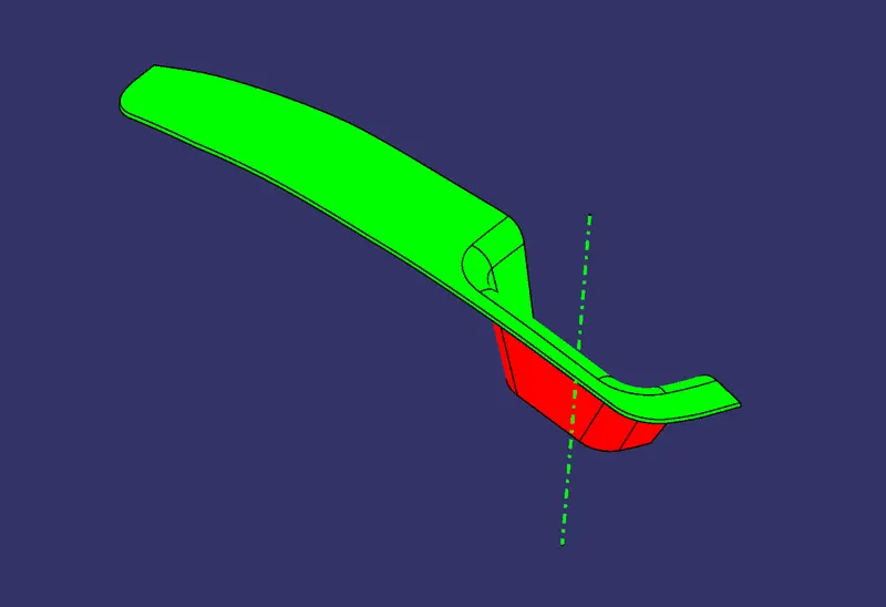
Switch Bezel Design
SWITCH BEZEL DESIGN
Creating Final Tooling Direction (Axis):
- For obtaining the final tooling direction, we will consider all the 3 axes and view the part along them.
- We extract the bottom surface and take a point at its center. Insert an axis system at this point with all the 3 axes along the original directions.
- After viewing the part in different views, we can conclude that direction along Z axis is appropriate for our tooling axis.
- For that we will consider tooling clearing along both X axis and Y axis.
- For X direction tooling clearing, as shown below, we take intersection of the given surface body along YZ plane of the new axis system.
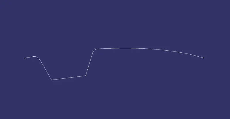
- Then we extend the lines in intersection that are inclined to Z axis as shown below.
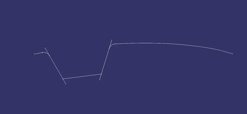
- Now create a line by bisecting these 2 lines as shown below.
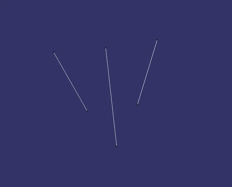
- Thus, the bisector line obtained is the X direction tooling clearing axis.
- Now for Y direction tooling clearing, we take sketch in XZ plane and take intersection of surface body along XZ plane.
- In that we draw a line along the inclined surface of intersection and one more line such that it is 6 degrees to the first line drawn. It will look something like as shown below. Turn the first line to construction as it may not be required later on.
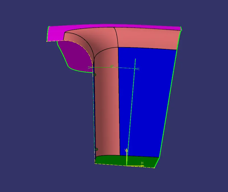
- Thus, the line obtained is the Y direction tooling clearing axis.
- Now, we create a line by bisecting these 2 lines (X and Y direction tooling clearing axes). Thus, we obtain the final tooling direction and axis along it.
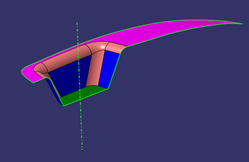
IMAGES
Draft Analysis and color scale variant
Class A Surface
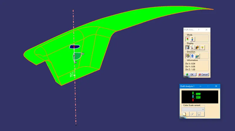
Solid Body
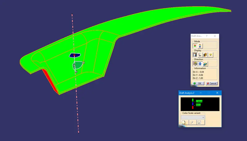
Tooling Direction
Model different views
Front view
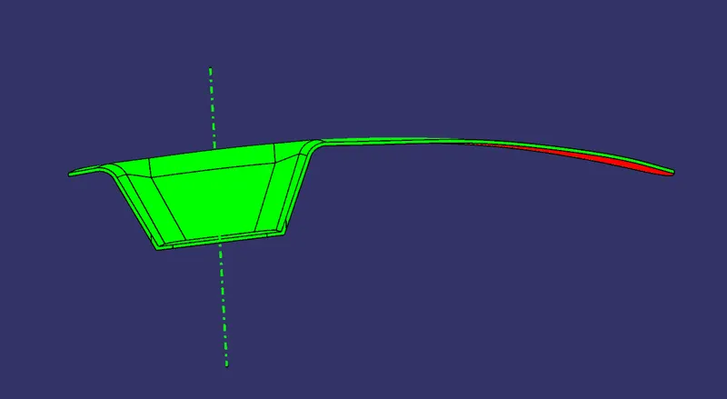
Side view
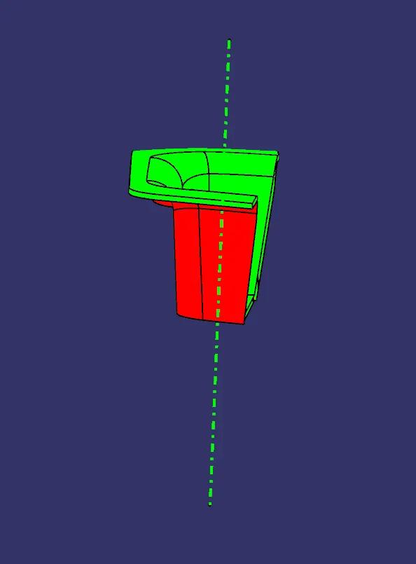
Top view
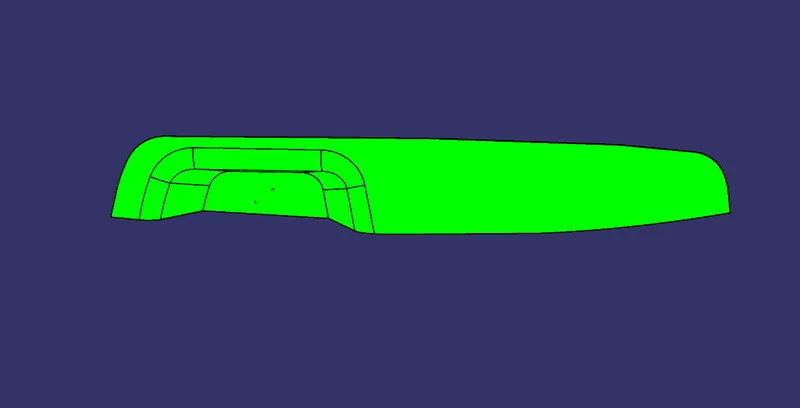
Isometric view