Week 8 - Challenge 3 - Switch Bezel Design
Switch Bezel design
Aim:
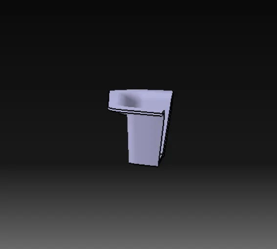
To design a Switch Bezel using the given class A surface
Procedure:
Check for connectivity:
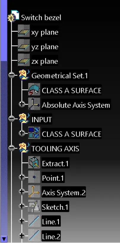
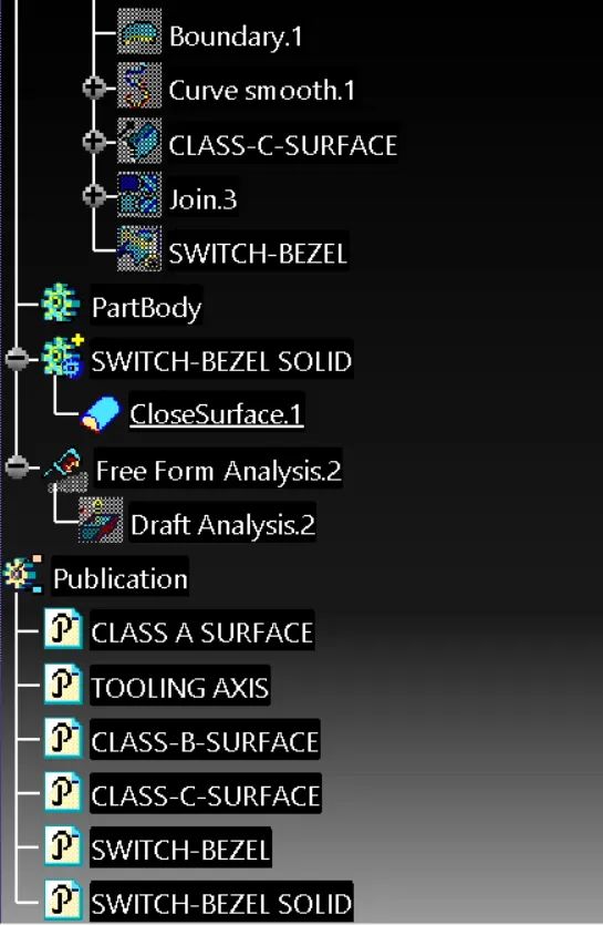
The given class A surface is checked for connectivity using joint and boundary tools in catia
Tooling direction:
- Inorder to create tooling direction the face of switch bezel is extracted and a point is created in this extract
- An axis is created in this point .As the switch bezel has only three wall the tooling direction is created using sketch.
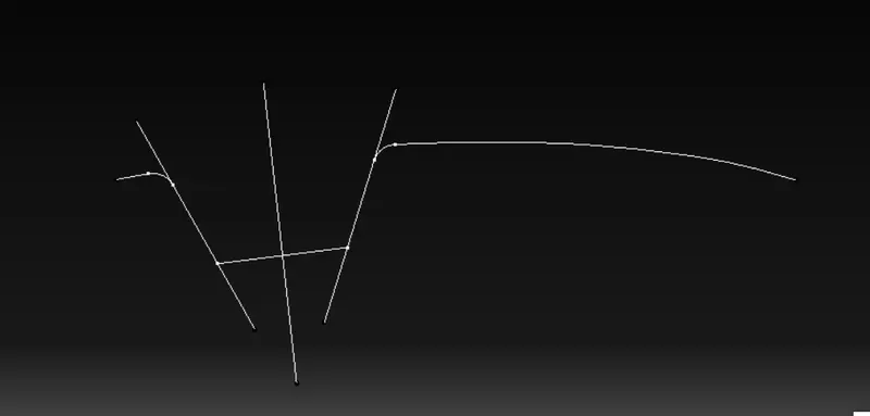
- A sketch is created in YZ axis using intersect 3D element.The side walls of the switch bezel is sketched using line and a bisecting wall is created between these two walls
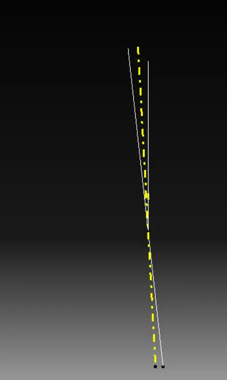
- Now a sketch is created in XZ axis here a line is created at 5 deg to the walls of switch bezel.
- Now a bisectig line is created these two sketches and this line is used as tooling axis.
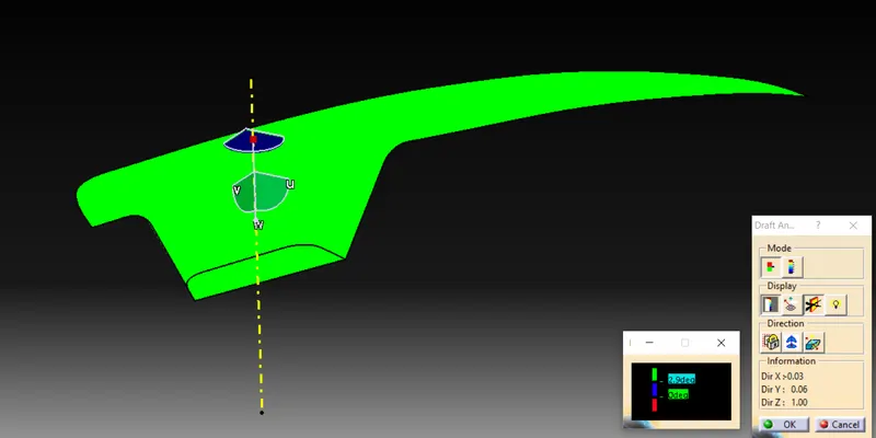
Draft analysis:
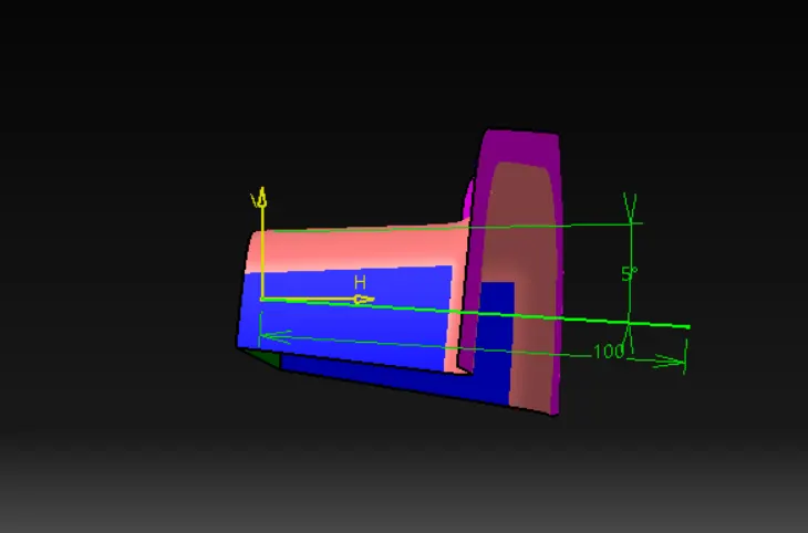
After creating tooling direction draft analysis is checked.
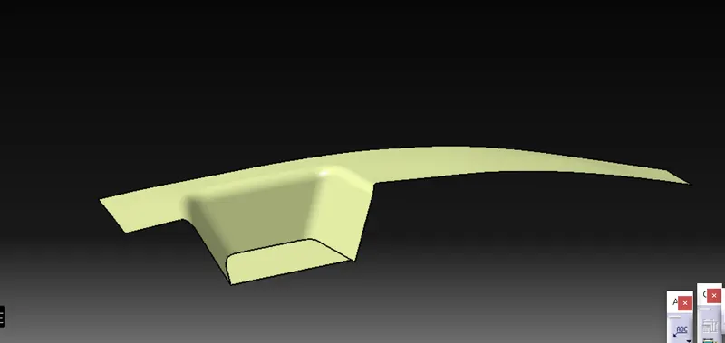
Creating class B surface:
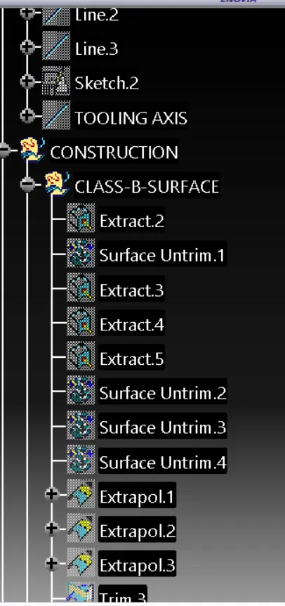
- Extract the surface from the class A surface and untrim it if necessary do extrapolate.
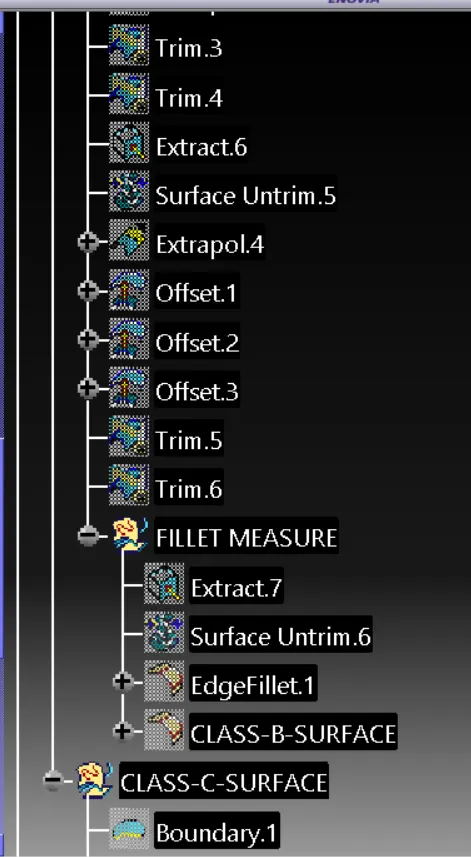
- After extrapolating the surface is trimmed to required shape and then it is offsetted to 2.5mm.
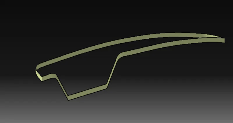
Creating class C surfaces:
- Class C surfaces is created to joint class A and class B surface.It is created using sweep command(sweep-line-with draft direction) and also using draft direction and draft angle as 3 deg.
- The outer boundary of the class A is taken using boundary and swept to create class C surface in required direction.
Final output:
- After creating surface C the surface A and surface C is jointed and then it is trimed using surface B.
- After getting required shape the surface is thicken using closed surface tool in part workbench.
Final draft analysis of the solid part:
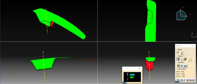
Draft analysis of Final solid:
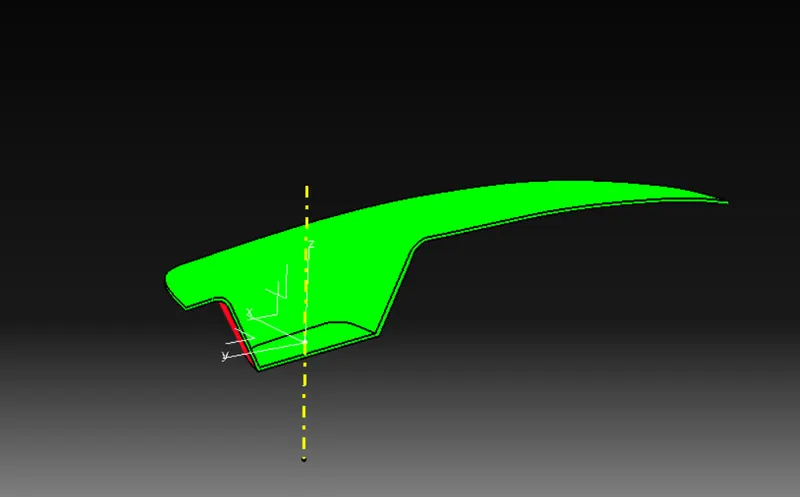
Draft analysis of class A surface:
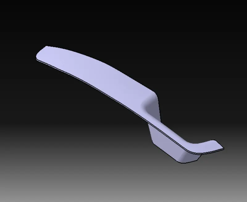
ISOMETRIC VIEW:
TOP VIEW:
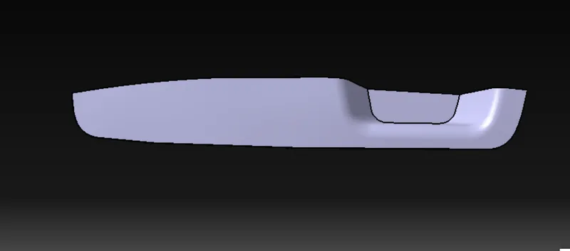
FRONT VIEW:
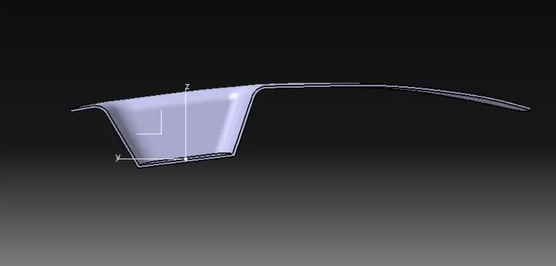
SIDE VIEW: